background image

9.

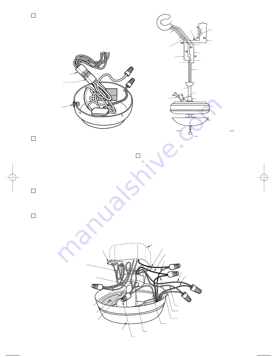
Using wire connectors (supplied),
make wiring connections as follows
(Figure 15 and 16):

a.

Connect the green ground wires
from the hanger bracket and the
hanger ball to the supply ground
wire (bare or green).

b.

Connect the white fan wire and the
white supply wire to the white
receiver wire (AC IN/MOTOR N).

c.

Connect the black fan wire to the
black receiver wire (TO MOTOR
L).

DOWNROD

MOTOR COUPLING

FAN HOUSING

OPTIONAL
LIGHT FIXTURE

YELLOW UPLIGHT WIRES
(NOT PRESENT ON ALL FANS)

RED AND BROWN
WIRES - CAPPED.
DO NOT REMOVE 
WIRE 
CONNECTORS

WHITE SUPPLY 
WIRE

BLACK FAN WIRE

RECEIVER

TO 110V 

SUPPLY

LISTED GENERAL
USE ON/OFF WALL
SWITCH OR 
OPTIONAL
EMERSON SW605
WALL CONTROL

YELLOW RECEIVER 
WIRE

**

WHITE FAN WIRE

BLUE RECEIVER WIRE

*

BLUE FAN WIRE

BLACK
SUPPLY
WIRE

WHITE RECEIVER 
WIRE

BLACK RECEIVER WIRE

BLACK/WHITE 
RECEIVER WIRE

* IF YOUR CEILING FAN DOES NOT 
HAVE A DOWNLIGHT,  CAP THE BLUE 
RECEIVER WIRE USING A WIRE 
CONNECTOR.

** IF YOUR CEILING FAN DOES NOT 
HAVE AN UPLIGHT, THERE WILL BE 
NO YELLOW FAN WIRE. 
IN THIS CASE, CAP THE YELLOW 
RECEIVER WIRE USING A WIRE 
CONNECTOR.

YELLOW FAN WIRE
(FROM UPLIGHT)

Figure 16

7.

Pull the wire leads, coming from the
end of the downrod, and the supply
wires through the open side of the
hanger bracket. (Figure 15).

8.

Position the RC188/RC212 Receiver in
the ceiling cover so that the flat side of
the receiver faces up and the open
portion of the receiver is to the right, as
shown in Figure 15.

OUTLET BOX

BLACK SUPPLY WIRE

BLACK/WHITE RECEIVER WIRE

BLACK FAN WIRE

BLUE FAN WIRE

BLUE RECEIVER 
WIRE

YELLOW FAN WIRE

YELLOW RECEIVER 
WIRE

CEILING COVER

WHITE RECEIVER WIRE

WHITE FAN WIRE

WIRE CONNECTOR

RECEIVER

WHITE SUPPLY
WIRE

SUPPLY 
GROUND
WIRE (GREEN 
OR BARE)

HANGER BALL
GROUND WIRE
(GREEN)

HANGER BRACKET
GROUND WIRE
(GREEN)

HANGER BRACKET

BLACK RECEIVER 
WIRE

OPEN PORTION 

OF RECEIVER 

HERE

Figure 15

PULL CHAIN 
PLUG

6-PIN WIRING 
CONNECTOR
FROM CEILINGFAN

6-PIN WIRING 
MODULE CONNECTOR
FROM SWITCH 
HOUSING

Figure 14

10

6.

Assemble your ceiling fan (including
the fan blades), install the hanger
bracket, and then hang the fan in
accordance with the instructions in the
Ceiling Fan Owner’s Manual. Wire the
ceiling fan and receiver and complete
the installation in accordance with the
following Steps 6 through 12.

5.

Connect the 6-pin wiring connector of
the module to the ceiling fan motor
assembly wiring connector. The
connectors are keyed and must be
mated correctly before they can be
engaged (Figure 14). 

BP7415 RC188 & RC212 Receiver  10/30/09  11:29 AM  Page 10

Summary of Contents for RC188

Page 1: ...755 CF770 CF775 CF940 CF935 CF670 CF690 CF695 RC212 Receiver and Module for Use Only with Emerson Ceiling Fan Model CF787 Receiver Model Numbers RC188 RC212 6 Speed Receiver RC188 Receiver Supplied with Reverse Module for 188 Motor Fans with Small Canopies RC212 Receiver Supplied with Reverse Module for 212 Motor Fans For Use With SR600 Remote Control SR650 Remote Control and SW605 Wall Control ...

Page 2: ...limits for a class B digital device pursuant to part 15 of the FCC Rules These limits are designed to provide reasonable protection against harmful interference in a residential installation This equipment generates uses and can radiate radio frequency energy and if not installed and used in accordance with the instructions may cause harmful interference to radio communications However there is no...

Page 3: ...ff the control Figure 1 2 Install two AAA alkaline batteries and reinstall the battery cover 3 General Your Emerson Ceiling Fan may be used with a SR600 or SR650 Remote Control a SW605 Wall Control and a RC188 RC212 6 speed Receiver The remote control or wall control is designed to control your ceiling fan speed airflow direction and light intensity NOTE The RC188 Receiver is to be used with the f...

Page 4: ...ion The blades will turn in the opposite direction and reverse the airflow 4 To set the desired fan speed press the button to decrease the speed and the to increase the speed The LED display will light up to indicate the new speed selected 5 To set the light intensity press and release the LIGHT button to decrease the light intensity and the LIGHT button to increase the light intensity The light w...

Page 5: ... for fluorescent bulbs Your remote control has code switches which must be set in one of 32 possible code combinations The five levers numbered 1 2 3 4 and 5 on the switches are factory set in the ON up position Change the switch settings as follows 1 Slide the five switch levers in the remote control to your choice of ON up or down positions Use a ball point pen or small screwdriver and slide the...

Page 6: ... the ceiling fan wall control into the outlet box 2 Remove faceplate and screws from existing wall control Pull control out from the wall box Determine the hot wire and the load wire and disconnect these wires from control Do not attempt to disconnect any wires not already connected to existing control 3 Before installing wall control place wall control in OFF mode by pushing ON OFF switch to the ...

Page 7: ...e ceiling fan wall control into the outlet box 2 At all wall box locations remove faceplates and screws from existing controls Pull controls out from wall boxes and determine which wall box contains the hot lead and which wall box contains the load wire Also identify traveler wires which are common to both wall boxes Disconnect wires from existing controls only Do not attempt to disconnect any wir...

Page 8: ...LOW FAN OFF LIGHT ON OFF HI MED LOW FAN OFF LIGHT ON OFF Figure 8 HOT BLK TRAVELER WIRES BLACK LOAD EXISTING WALL CONTROL FAN LIGHT WALL CONTROL BLK BLACK LOAD TRAVELER WIRES HOT BLK EMERSON EMERSON BLK BLK HI MED LOW FAN OFF LIGHT ON OFF HI MED LOW FAN OFF LIGHT ON OFF 3 WAY WIRING DIAGRAM RETROFIT Figure 9 Operation of Your Wall Control Figure 10 Your wall control has full control of your fan an...

Page 9: ...ing Figure 11 2 All Ceiling Fan Models Disconnect the motor connector from the wiring harness connector Figure 11 Remove the knurled nut securing the speed control switch to the switch housing and place the pull chain plug in the exposed hole KNURLED NUT SPEED CONTROL SWITCH PULL CHAIN PLUG REVERSING SWITCH SWITCH HOUSING CAPACITOR MOTOR CONNECTOR WIRING HARNESS CONNECTOR SCREW 2 Figure 11 NOTE Ke...

Page 10: ...e wire leads coming from the end of the downrod and the supply wires through the open side of the hanger bracket Figure 15 8 Position the RC188 RC212 Receiver in the ceiling cover so that the flat side of the receiver faces up and the open portion of the receiver is to the right as shown in Figure 15 OUTLET BOX BLACK SUPPLY WIRE BLACK WHITE RECEIVER WIRE BLACK FAN WIRE BLUE FAN WIRE BLUE RECEIVER ...

Page 11: ...1 4 THREADED STUDS 2 Figure 17 12 Slide the receiver up and over the hanger bracket Press the receiver against the ceiling holding it in place while installing the ceiling cover in accordance with the instructions in the Ceiling Fan Owner s Manual 13 Install the optional Emerson Light Fixture in accordance with the instructions in the Light Fixture Owner s Manual Use the screws removed in Step 1 N...

Page 12: ...ponsible for any such damage What Is Not Covered This warranty also does not cover any defects malfunctions or failures caused by Repairs by persons not authorized by Emerson Electric Co Use of parts or accessories not authorized by Emerson Electric Co Mishandling improper installation modifications or damage to your receiver while in your possession or Unreasonable use misuse abuse including fail...

Reviews: