4.
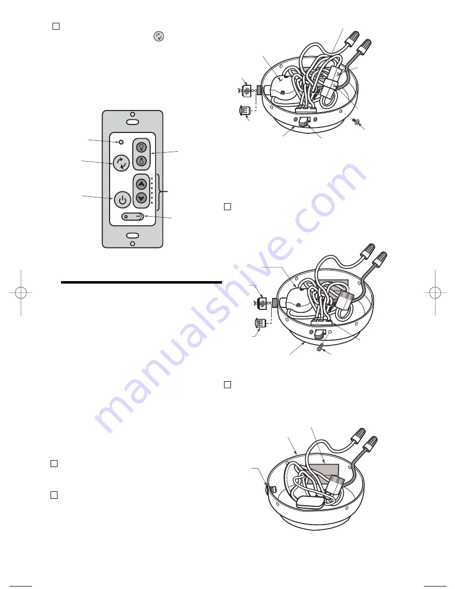
If airflow is desired in the opposite
direction, press the ( ) button on the
wall control. The fan must be operating
at any speed for the reverse button to
function. The blades will turn in the
opposite direction and reverse the
airflow.
LIGHT
BUTTON
HIGH TO LOW
SPEED BUTTONS
FAN
DIRECTION
POWER
INDICATOR
LIGHT
FAN
BUTTON
ON/OFF SWITCH
O = OFF / — = ON
Figure 10
9
CEILING FAN
PROCEDURES
Installation to Operate the
Ceiling Fan, Downlight
and Uplight
IMPORTANT
It is important that you also follow the
installation instructions contained in
the Owner’s Manual supplied with your
Ceiling Fan. Pay particular attention to
the Safety Instructions and WARNING
notes.
1.
Remove and retain the screws
securing the housing cover to the
switch housing (Figure 11).
2. All Ceiling Fan Models.
Disconnect
the motor connector from the wiring
harness connector (Figure 11).
Remove the knurled nut securing the
speed control switch to the switch
housing and place the pull chain plug in
the exposed hole.
KNURLED
NUT
SPEED
CONTROL
SWITCH
PULL
CHAIN PLUG
REVERSING
SWITCH
SWITCH HOUSING
CAPACITOR
MOTOR
CONNECTOR
WIRING
HARNESS
CONNECTOR
SCREW (2)
Figure 11
NOTE: Keep the uplight switch if you
think you may like to return to manual
control in the future.
SECTION THREE:
KNURLED
NUT
SPEED CONTROL
SWITCH
PULL
CHAIN PLUG
SWITCH HOUSING
SCREW (2)
REVERSING
SWITCH
Figure 12
3.
Remove two screws securing the
reversing switch to the switch housing
and place the pull chain plug in the
exposed hole.(Figure 12).
SWITCH HOUSING
RC188/RC212 MODULE
PULL
CHAIN
PLUG
Figure 13
4.
Remove the speed control switch and
reversing switch capacitor. Position the
RC188/RC212 module into the switch
housing (Figure 13).
BP7415 RC188 & RC212 Receiver 10/30/09 11:29 AM Page 9


