background image

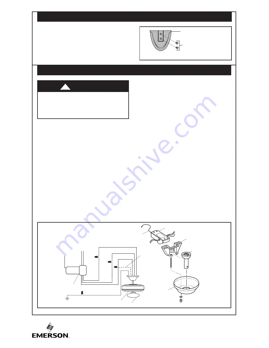
7. Installation of Storage Bracket 

(Figure 4)

4

U.L. Model No: MR101F

STORAGE BRACKET

STORAGE BRACKET

SCREWS (2)

Figure 4

A storage bracket is provided for holding your

transmitter when not in use. If you desire to

use  the  storage  bracket,  install  it  on  a  wall

that  is  away  from  excess  heat  or  humidity.

Use  the  two  screws  provided  with  storage

bracket.

BARE

GREEN/GROUND

AN

TE

NN

A

W

HI

TE

TO

AC SUPPLY

WHITE

BLACK

BLUE

BL

AC

K

BL

UE

RECEIVER

RE

D

HANGER

BALL

CEILING

COVER

ANTENNA

HANGER

BRACKET

RECEIVER

W

HI

TE

FAN HOUSING

LIGHT

YELLOW

(if present)

Note: 

Make all wiring connections using only

listed wire connectors (supplied).  Make sure

all  connections  are  tight,  including  ground,

and  no  bare  wire  is  visible  at  the  wire

connectors,  except  for  the  supply  circuit

ground wire.

1.

After electricity has been turned off at main

fuse box or circuit breaker box, remove the

ceiling cover from the hanger bracket.

2.

Disconnect the supply wiring to the fan by

removing wire connectors.

Note: 

Do  not  disconnect  the  BARE/GREEN

GROUND wires.

3.

Connect  the  supply  BLACK  wire  to  the

receiver RED wire (AC IN L). 

4.

Connect  the  supply  WHITE  wire  to  the

receiver WHITE wire (AC IN N).

To avoid possible electrical shock, be

sure  electricity  is  turned  off  at  the

main  fuse  or  circuit  breaker  box

before installing the receiver.

5.

Connect  the  receiver  WHITE  wire

(TO MOTOR N) to the fan WHITE wire.

6.

Connect  the  receiver  BLACK  wire

(TO MOTOR L) to the fan BLACK wire. 

7.

Connect  the  receiver  BLUE  wire  (FOR

LIGHT)  to  the  fan  BLUE  wire  and  fan

YELLOW wire (if present).

Note: 

This  wiring  configuration  will  control

the  up  light  and  down  light  together.

A  maximum  of  300W  total  lighting  can  be

used  with  this  receiver.  Exceeding  this

wattage  will  damage  the  receiver  and  void

the warranty.

CAUTION:  If  no  light  exists  on  your

ceiling  fan,  cap  the  BLUE  wire  on  the

receiver with a wire connector.

8.

Push  the  connected  wires  up  into  the

junction  box  and  position  the  receiver  in

the hanger bracket above the hanger ball.

Lay  the  antenna  wire  on  top  of  the

receiver.

9.

Reinstall  the  ceiling  cover  and  restore

electrical power to the circuit.

Figure 5

8. Installation of Receiver

(Figure 5)


WARNING

!

Summary of Contents for RCBT100

Page 1: ... in the ceiling cover Before installing or servicing the ceiling fan or receiver switch power off at service panel and lock service panel to prevent power from being switched on accidentally If the service panel cannot be locked securely fasten a warning device such as a tag to the service panel ADDITIONAL SAFETY INSTRUCTIONS FOR INSTALLATION 1 To avoid possible electrical shock be sure electricit...

Page 2: ...ining the Bluetooth Ceiling Fan Control Remove contents and check to see that you have received the following parts 1 Transmitter 1 2 Storage Bracket and Hardware 1 set 3 A23 MN21 12V Alkaline Battery 1 4 Receiver 1 Your Emerson Bluetooth Ceiling Fan Control consists of a hand held transmitter and a receiver The transmitter is designed to separately control your ceiling fan speed and light intensi...

Page 3: ...d ON and DIM is for dimming control of lights Set switch to DIM to allow for dimming of the lights Set switch to ON for full brightness of the lights such as for fluorescent bulbs 4 Reinstall the battery compartment cover onto the transmitter Figure 1 CODE SWITCHES RECEIVER TRANSMITTER DIM SWITCH DIP 1 2 3 4 ON ON DIM A23 DIP 1 2 3 4 ON 4 3 2 1 Figure 2 4 Installation of Battery Figure 1 5 Setting...

Page 4: ...Do not disconnect the BARE GREEN GROUND wires 3 Connect the supply BLACK wire to the receiver RED wire AC IN L 4 Connect the supply WHITE wire to the receiver WHITE wire AC IN N To avoid possible electrical shock be sure electricity is turned off at the main fuse or circuit breaker box before installing the receiver 5 Connect the receiver WHITE wire TO MOTOR N to the fan WHITE wire 6 Connect the r...

Page 5: ...ting System OS software to download AndroidTM Version 6 0 or Later iOS version 10 0 or Later Note In the Apple App Store the Emerson Bluetooth Ceiling Fan Control App will ONLY appear on an iPhone only search On an iPad this will have to be changed in the App Store Figure 6 1 Ensure power has been restored to your fan after installing the receiver and Bluetooth is enabled on your device If Bluetoo...

Page 6: ... your fan 2 Once you have made your selection you will be prompted to name your fan Enter the desired name and select Confirm Figure 10 3 After confirming the name follow the on screen prompts to complete the configuration of your fan Figure 9 Figure 10 1 To rename your fan press the Edit Name button in the upper right hand corner of the fan control screen Figure 11 2 You will be prompted to name ...

Page 7: ...fan 6 Use the Light Power button to turn the light ON and OFF 7 Use the slider under Light Power to control the brightness of the lights if dimming is enabled 8 Use the slider under Auto Off Timer to set the number of hours and minutes until your fan and lights turn off 15 Operating Your Fan Figure 13 1 If additional Emerson Bluetooth Ceiling Fan Controls have been purchased and installed they can...

Page 8: ...ir Comfort Products Division of Emerson Company 8100 W Florissant Ave St Louis MO 63136 Include all model numbers shown on the product with your request To return the product to an authorized service center call 1 800 654 3545 for the address of the nearest authorized service center You will be responsible for all insurance freight or other transportation charges to our factory or authorized servi...

Reviews: