


ROC364 Instruction Manual
2-9
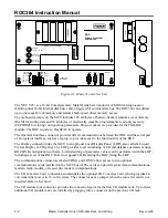
Master Controller Unit, I/O Module Rack, and Wiring
Rev Jun/05
2.3.4 Installing a FlashPAC Module
Use the following procedure to add a FlashPAC module. This procedure assumes the first-time
installation of a FlashPAC module in an out-of-service ROC. For an in-service ROC, refer to the Section
2.5.10, Replacing a FlashPAC, on page 2-16.
Equipment and Tools Required:
None
When working on units located in a hazardous area (where explosive gases may be present), make
sure the area is in a non-hazardous state before performing these procedures. Performing these
procedures in a hazardous area could result in personal injury or property damage.
1.
Remove the FlashPAC module retainer by unscrewing the two thumbscrews and sliding the
retainer straight out.
2.
Remove and discard the foam insert that blocks the unused slot in the retainer.
Before installing a FlashPAC module, make sure the module connector pins are not bent. Bent
pins can damage the mating connector. Do not attempt to straighten bent pins; instead, replace
the module.
3.
Align the key on the module socket with the key of the MCU socket; in this position, the “F” of
“FlashPAC” on the label should be closest to the I/O terminals.
4.
Carefully insert the module in the socket and press it in firmly, but gently to seat the module. The
module should move inward slightly. Verify that the module is seated in the connector by gently
lifting up on the module. If it comes out easily, repeat the process.
5.
Carefully position the retainer over the FlashPAC, and tighten the thumbscrews. Make sure that
the sloped surface of the retainer is down.
2.4 Connecting the MCU to Wiring
The following paragraphs describe how to connect the ROC to power, ground, and communications
wiring. For connections to I/O modules, refer to Section 3. To wire a communications card, refer to
Section 4.
The power and I/O wiring terminal blocks accept up to 12-gauge AWG solid or stranded copper wire.
NOTE:
Use a standard screwdriver with a slotted (flat bladed) 1/8-inch width tip when wiring all
terminal blocks.
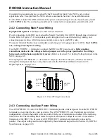
2.4.1 Connecting Ground Wiring
Equipment Required:
Flat-blade (1/8-inch wide) screwdriver
The ROC and related components must be connected to earth ground. These include the MCU,
I/O module racks, system I/O devices, and the system power source. Each component connects to
earth ground (typically an enclosure ground bar) using the grounding screw provided. The components
should be linked using an 18 AWG or greater conductor. The earth ground wire from the ROC enclosure
ground bar to ground should be at least 12 AWG.


