NOTE
The user must provide a means to discon-
nect the main power supply in the form of
circuit breaker or switch. The circuit break-
er or the switch must be located in close
proximity to the instrument and identified
as the disconnecting device for the instru-
ment.
2.4.1 Power Input Wiring.
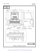
The Model 1054B can be
configured for either 115 VAC or 230 VAC power.
Connect AC power to TB1-7 and -8 (230V), or TB1-8
and -9 (115 VAC) ground to the TB3-8 (refer to
Figure 2-6).
1.
AC connections and grounding must be in com-
pliance with UL 508 and/or local electrical codes.
2.
The metal stiffener is required to provide support
and proper electrical continuity between conduit
fittings.
3.
This type 4/4X enclosure requires a conduit hub
or equivalent that provides watertight connect,
REF UL 508-26.10.
4.
Watertight fittings/hubs that comply with the
requirements of UL 514B are to be used.
5.
Conduit hubs are to be connected to the conduit
before the hub is connected to the enclosure, REF
UL 508-26.10.
6.
If the metal support plate is not used, plastic fit-
tings must be used to prevent structural damage
to the enclosure. Also, appropriate grounding lug
and awg conductor must be used with the plastic
fittings.
2.4.2 Output Wiring.
The signal output and alarm
connections are made to terminals 1 through 6 of TB1
and terminals 1 and 2 of TB3 (refer to Figure 2-6).
CAUTION
The sensitivity and stability of the analyzer
will be impaired if the input wiring is not
grounded. DO NOT apply power to the
analyzer until all electrical connections are
verified and secure. The following precau-
tions are a guide using UL 508 as a safe-
guard for personnel and property.
4
MODEL 1054B pH/ORP
SECTION 2.0
INSTALLATION
2.4 ELECTRICAL WIRING.
The Model 1054B has
three conduit openings in the bottom rear of the
analyzer housing which will accommodate
1/2
-inch
conduit fittings. From a back view, the conduit open-
ing on the left is for timer, alarm, and AC connec-
tions; the center is for signal output and the opening
on the right is for sensor wiring. AC power wiring
should be 14 gauge or greater.
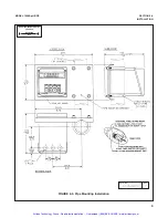
The wall mount enclosure has three
3/4
-inch conduit
openings, two with
3/4
-inch fittings and one with a
NEMA 4X conduit plug. From the front view the
conduit opening on the left is for sensor wiring; the
center is for signal output, and the right is for timer,
alarm and AC power supply connections. Sensor
wiring should always be run in a separate conduit
from power wiring.
NOTE
Wall mount: use opening on the left for sensor
wiring (refer to Figure 2-4 for wiring).
NOTE
PN 23363-00 (integral preamplifier). Refer to
Figure 2-7 for installation and wiring. PN 23508-
00 (integral preamp is for wall mount enclo-
sure). Refer to Figure 2-9.
NOTE
For maximum EMI/RFI protection the output
cable should be shielded and enclosed in an
earth grounded, rigid metal conduit. When
wiring directly to the instrument connect the
output cable‘s outer shield to the transmitter’s
earth ground via terminal 8 on TB3, Fig. 2-6.
When wiring to the wall mounting junction box
connect the output cable’s outer shield to earth
ground via terminal 6 of TB-A, Fig. 2-4.
The sensor cable should also be shielded.
When wiring directly to the instrument connect
the sensor cable’s outer shield to the transmit-
ter’s earth ground via terminal 8 of TB2, Fig. 2-
6. If the sensor cable’s outer shield is braid an
appropriate metal cable gland fitting may be
used to connect the braid to earth ground via
the instrument case. When wiring to the wall
mounting junction box connect the cable’s
outer shield to earth ground via terminal 6 of
TB-A, Fig. 2-4.
Artisan Technology Group - Quality Instrumentation ... Guaranteed | (888) 88-SOURCE | www.artisantg.com


