background image

www.rosemount.com

Reference Manual

00809-0100-4029, Rev AA
July 2005

Rosemount 2110

S

ECTION


2

I

NSTALLATION

Safety Messages   . . . . . . . . . . . . . . . . . . . . . . . . . . . . . . . . . . . . . . . . . . . . page 2-1
Mechanical Installation   . . . . . . . . . . . . . . . . . . . . . . . . . . . . . . . . . . . . . . . page 2-1
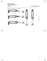
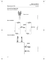
Correct Fork Alignment  . . . . . . . . . . . . . . . . . . . . . . . . . . . . . . . . . . . . . . . page 2-2
Electrical Installation  . . . . . . . . . . . . . . . . . . . . . . . . . . . . . . . . . . . . . . . . . page 2-4

Safety Messages

Procedures and instructions in this manual may require special precautions to ensure the 
safety of the personnel performing the operations. Information that raises potential safety 
issues is indicated by a caution symbol (

). The external hot surface symbol (

)is used 

when a surface is hot and care must be taken to award possible burns. If there is a risk of an 
electrical shock the (

)symbol is used. Refer to the safety messages listed at the 

beginning of each section before performing an operation preceded by this symbol.

Mechanical Installation

Figure 2-1. Sealing

Figure 2-2. Tighten the Switch

Gasket

BSPP (G1)

NPT, BSPT (R)

Seal (supplied in 
02100-1020-0001)

Tri-Clamp

PTFE (Teflon)

21

10

/21

1

0_

28a

a

, 21

10

_2

9a

a.e

p

s

4029 Rev AA Book.book  Page 1  Wednesday, July 6, 2005  8:09 AM

Summary of Contents for Rosemount 2110

Page 1: ...Reference Manual 00809 0100 4029 Rev AA July 2005 www rosemount com Rosemount 2110 Compact Vibrating Fork Liquid Level Switch ...

Page 2: ......

Page 3: ... designed for nuclear qualified applications Using non nuclear qualified products in applications that require nuclear qualified hardware or products may cause inaccurate readings For information on Emerson Process Management nuclear qualified products contact your local Emerson Process Management Sales Representative CAUTION Rosemount pursues a policy of continuous development and product improve...

Page 4: ...Reference Manual 00809 0100 4029 Rev AA July 2005 Rosemount 2110 ...

Page 5: ...eak Detection 1 3 Pump Control 1 3 Hygienic Applications 1 3 Application Considerations 1 4 Handling the 2110 1 4 Rosemount Identification 1 6 Installation Considerations and Recommendations 1 7 Switchpoint 1 8 Service Support 1 9 Warranty 1 9 SECTION 2 Installation Safety Messages 2 1 Mechanical Installation 2 1 Correct Fork Alignment 2 2 Pipe Installation 2 2 Vessel Installation 2 2 Cover Orient...

Page 6: ...arts 3 2 APPENDIX A Reference Data Physical Specifications A 1 Mechanical A 1 Performance Specifications A 2 Functional Specifications A 2 Electrical A 3 Dimensional Drawing A 5 Ordering Information A 6 Accessories A 7 APPENDIX B Product Certifications L V Directive B 1 Electro Magnetic Compatibility EMC Directive B 1 Overfill Protection B 1 Approved Manufacturing Locations B 1 ...

Page 7: ...s symbol Failure to follow these installation guidelines could result in death or serious injury Protection afforded by compliance to EN61010 1 2001 may be impaired if the equipment is not used as specified The Rosemount 2110 is a liquid level switch It must be installed connected commissioned operated and maintained by suitably qualified personnel only observing any national and local requirement...

Page 8: ...ssel and pipe Using Short Fork Technology the Rosemount 2110 is designed for use in virtually all liquid applications Extensive research has maximized the operational effectiveness of the fork design making it suitable for almost all liquids including coating liquids avoid bridging of forks aerated liquids and slurries Rosemount 2110 Application and Mounting Examples For most liquids including coa...

Page 9: ...00 barg making it perfect for use as a high or low level alarm It is common practice to fit an independent high level alarm switch to provide extra back up to the level switch in case of failure Leak Detection Flanges gaskets seals corrosive liquids they all have the potential to leak at the most inconvenient times Many users site tanks and vessels above trays or in containments to prevent any liq...

Page 10: ...0 kg m3 Examples of products with too low of density is acetone pentane and hexane Check for risk of build up on the forks Avoid situations where drying and coating products may create excessive build up Ensure no risk of bridging the forks Examples of products that can create bridging of forks are dense paper slurries and bitumen Check if solid content in liquid Problems may occur if product coat...

Page 11: ...Reference Manual 00809 0100 4029 Rev AA July 2005 Rosemount 2110 1 5 Figure 1 2 Do not alter the 2110 in any way 2110 2110_27aa eps ...

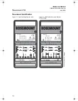
Page 12: ... 500mA 40 80 C amb T 40 150 C op 21 264V AC 50 60Hz DC LED 20mA 500mA 3mA 1Hz on Hi Alarm Lo Alarm NC NC 2 1 3 1 3 1 2 1 2 3 N 0V L1 V L1 V N 0V 1 3 1 2 MAGNETIC TEST POINT 211002RNA 2 in Tri Clamp LED 500mA 1Hz on Hi Alarm Lo Alarm 2 3 3 2 3 2 2 3 2 3 V 0V PLC 0V V PLC 1 1 2 3 Sig Sig Low Voltage PNP type www rosemount com Model Fitting MAGNETIC TEST POINT IP66 67 I 500mA 40 80 C amb T 40 150 C o...

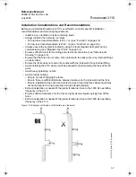
Page 13: ...tank wall or any internal fittings or obstructions Ensure the forks does not come into contact with the tank wall of any internal fitting Avoid installing the 2110 where it will be exposed to liquid entering the tank at the fill point Avoid heavy splashing on fork Avoid product buildup Ensure no risk of bridging the forks Ensure there is sufficient distance between build up on the tank wall and th...

Page 14: ...nt 2120 fig12 eps Switchpoint H20 SP Switching hysteresis HY 0 039 in 1 mm 0 039 in 1 mm 0 5 in 13 mm 0 5 in 13 mm 0 5 in 13 mm In the top diagram a lower density media will give switchpoint closer to the connection A higher density media will give switchpoint closer to fork tip ...

Page 15: ...ional information and procedures necessary to return goods exposed to hazardous substance can avoid injury if they are informed of and understand the hazard If the product being returned was exposed to a hazardous substance as defined by OSHA a copy of the required Material Safety Data Sheet MSDS for each hazardous substance identified must be included with the returned goods Warranty Emerson Proc...

Page 16: ...Reference Manual 00809 0100 4029 Rev AA July 2005 Rosemount 2110 1 10 ...

Page 17: ...he operations Information that raises potential safety issues is indicated by a caution symbol The external hot surface symbol is used when a surface is hot and care must be taken to award possible burns If there is a risk of an electrical shock the symbol is used Refer to the safety messages listed at the beginning of each section before performing an operation preceded by this symbol Mechanical ...

Page 18: ... 00809 0100 4029 Rev AA July 2005 Rosemount 2110 2 2 Correct Fork Alignment Ensure correct fork alignment Pipe Installation Vessel Installation 2110 14aa eps Alignment groove 2110 24aa 2110_16aa eps 2110 2110_34aa tif ...

Page 19: ...Reference Manual 00809 0100 4029 Rev AA July 2005 Rosemount 2110 2 3 Cover Orientation 2110 2110_36aa eps ...

Page 20: ...und WET ON Low level alarm PE Ground PE Ground Maximum inrush current 5A Over current protected I Maximum continuous 500 mA I Minimum continuous 20mA Supply current 3mA nominal Voltage drop 6 5V 24V dc 5 0V 240 V ac Voltage drop 3V I Load off 3mA I Load off 0 5mA 1 3 R 2A T 21 264V ac 50 60Hz 21 264V dc L1 V N 0V 1 3 R 2A T 2 0V V 18 60V dc PLC Input 1 R 2A T 21 264V ac 50 60Hz 21 264V dc L1 V N 0...

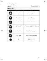
Page 21: ...Switch Status Continuous Output state is on 1 every second Output state is off 1 every 2 seconds Uncalibrated 1 every 4 seconds Load fault load current too high load short circuit 2 times second Indication of successful calibration 3 times second Internal fault micro ROM or RAM Off Problem e g supply ...

Page 22: ... ac dc LED LED on continuously LED flashes every second LED on continuously LED flashes every second 1 2 3 PLC I P 3V U IL 1 2 3 PLC I P IL 100uA PLC 1 2 3 I P 3V U IL PLC 1 2 3 I P IL 100uA 1 2 3 3V U V 0V IL 100uA 1 2 3 V 0V 1 2 3 3V U V 0V V 0V IL 100uA 1 2 3 1 3 12V U V 0V L1 N V 0V 3mA 1 3 L1 N 1 2 12V U V 0V L1 N V 0V 3mA 1 2 L1 N Load On Load Off ...

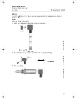
Page 23: ...lied connector and suitable cable NOTE Use only connector supplied 1 Insert cable into plug housing and connect to terminals 2 Ensure both seals are in place to maintain the weatherproof rating 3 Fit plug to body Maximum 0 31 8 Minimum 0 24 6 5 9 1 5 2110 2110_15aa eps 2110 2110_15ab eps Screw Seal Plug Seal Fixing Screw 2110 2110_28ac eps ...

Page 24: ...e user must ensure that the drop out voltage of the relay is greater than the voltage which will be generated across the relay coil when 3mA flows through it NOTE FOR DIRECT LOAD SWITCHING DPST Double Pole Single Throw on off switch must be fitted for safe disconnection of the power supply Fit the switch as near to the 2110 as possible Keep the switch free of obstructions Label the switch to indic...

Page 25: ...llowing a functional test of the 2110 By touching a magnet on the target the 2110 output will change state for as long as the magnet is present Inspection Visually examine the 2120 for damage If it is damaged do not use Check connector and seals are correctly fitted also that the connector fixing screw and gland are tight Ensure the LED flash rate is 1 Hz or continually on If anything else is demo...

Page 26: ... on direct load switching electronics model LED 3 flashes per second Internal failure contact supplier LED 1 flash every 2 seconds Uncalibrated return to supplier LED 1 flash every 4 seconds Load fault load current too high load short circuit check installation Fork damaged Replace Thick encrustation on forks Clean the fork with care 5 second delay on changing mode delay Wait 5 seconds Incorrect s...

Page 27: ... and slurries Mechanical Process material 316L Stainless Steel 1 4404 For Tri Clamp connection hand polished to better than 0 8 μm Gasket material for 1 in BSPP G1 is Non asbestos BS7531 Grade X carbon fiber with rubber binder Housing materials Body 304 SST with polyester label LED window Flame retardant Polyamide Pa12 UL94 V2 Plug Polyamide glass reinforced Plug seals Nitrile butadiene rubber 122...

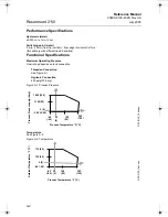
Page 28: ...ecifications Maximum Operating Pressure Final rating depends on tank connection Threaded Connection See Figure A 1 Hygienic Connection 435 psig 30 barg Figure A 1 Process Pressure Temperature See Figure A 2 Figure A 2 Temperature 1450 100 1160 80 3 62 0 25 40 40 122 50 302 150 Process Temperature F C Process Pressure psig barg 2120 2120_18ab eps 0 0 32 0 176 80 140 60 40 40 40 40 302 150 Process T...

Page 29: ...ce Cleaning Withstands steam cleaning routines up to 302 F 150 C Electrical Switching mode User selectable Dry on or Wet on by selecting plug wiring Cable connection Via 4 way plug provided DIN43650 Max conductor size 15AWG Orientation 4 position 90 180 270 360 deg Conductor size Maximum 0 06 inch2 1 5 mm2 Cable gland PG9 provided cable diameter 0 24 to 0 31 in 6 to 8 mm Protection Reverse polarit...

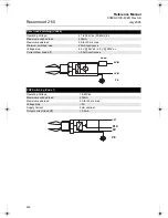
Page 30: ...0mA Maximum peak load 5A for 40 ms max Minimum switched load 20mA continuous Voltage drop 6 5V 24V dc 5 0V 240V ac Current draw load off 3 0mA continuous PNP Switching Code 1 Operating Voltage 18 60V dc Maximum switched load 500mA Maximum peak load 5A for 40 ms max Voltage drop 3V Supply Current 3mA nominal Output current load off 0 5mA Load 0V N V N PE V PLC 0V PE ...

Page 31: ... 72 69 1 97 50 7 40 188 N A 1 in BSPT R 2 72 69 1 97 50 7 40 188 N A 1 in BSPP G 3 07 78 2 36 60 7 91 201 N A 2 in 51 mm Tri Clamp 2 72 69 1 97 50 7 40 188 2 52 64 1 in Semi extended 4 57 116 3 86 98 9 41 239 N A 2110 06aa eps C 0 51 13 Switchpoint B D A 41 A F Thread 1 in or 3 4 in Notch to indicate fork orientation 1 50 38 External Earth Point Connector Cable Gland Supplied 2 in Tri Clamp 0 51 1...

Page 32: ... 60 V dc Code Process Connection Size Type 0A 3 4 in BSPT R thread 1A 1 in BSPT R thread 0D 3 4 in NPT thread 2R 2 in 51mm Tri clamp 1B 1 in BSPP G thread 1L 1 in BSPP G Semi extended 4 6 in 116 mm Code Product Certificates NA No Hazardous Locations Certifications safe area use only Overfill U1 DIBt WHG Overfill protection Code Options Calibration Data Certificate Q4 Certificate of functional test...

Page 33: ...on asbestos BS7531 grade X carbon fiber with rubber binder 02100 1010 0001 Hygienic adaptor boss 1 in BSPP Material 316 SS fitting Viton O ring 02100 1020 0001 2 in 51 mm Tri clamp kit including vessel fitting clamp ring seal Material 316 St steel NBR Nitrile 02100 1030 0001 Telescopic test magnet 1 54 39 1 30 34 0 12 3 1 20 30 5 1 in BSPP 2 36 60 0 18 4 5 1 54 39 ...

Page 34: ...Reference Manual 00809 0100 4029 Rev AA July 2005 Rosemount 2110 A 8 ...

Page 35: ...facturing Locations page B 1 L V Directive page B 1 Overfill Protection page B 1 L V Directive EN61010 1 Pollution degree 2 Category II 264V max Pollution degree 2 Category III 150V max Electro Magnetic Compatibility EMC Directive EN61326 Overfill Protection Option available for DIBt WHG Approved Manufacturing Locations Slough UK ...

Page 36: ...Reference Manual 00809 0100 4029 Rev AA July 2005 Rosemount 2110 B 2 ...

Page 37: ......

Page 38: ...Process com 00809 0100 4029 Cover Photos 2110 2110 clear_rev 2110 hyg_rev Rosemount and the Rosemount logotype are registered trademarks of Rosemount Inc PlantWeb is a registered trademark of one of the Emerson Process Management group of companies HART is a registered trademark of the HART Communication Foundation Teflon VITON and Kalrez are registered trademarks of E I du Pont de Nemours Co FOUN...

Reviews: