background image

Quick Start Guide

00825-0100-2501, Rev AA

October 2019

Rosemount

 2501 Solids Level Switch

Rotating Paddle

Summary of Contents for Rosemount 2501

Page 1: ...Quick Start Guide 00825 0100 2501 Rev AA October 2019 Rosemount 2501 Solids Level Switch Rotating Paddle ...

Page 2: ...Contents Introduction 3 Mechanical installation 11 Electrical installation 20 Configuration 25 Operation 28 Maintenance 31 Product certifications 33 Quick Start Guide October 2019 2 Quick Start Guide ...

Page 3: ...oting and order related questions United States 1 800 999 9307 7 00 am to 7 00 pm CST Asia Pacific 65 777 8211 North American Response Center Equipment service needs 1 800 654 7768 24 hours a day includes Canada Outside of these areas contact your local Emerson representative WARNING Physical access Unauthorized personnel may potentially cause significant damage to and or misconfiguration of end u...

Page 4: ...insulation is suitable for the voltage temperature and environment Process leaks could result in death or serious injury Ensure the level switch is handled carefully If the process seal is damaged gas or dust might escape from the silo or other vessel Any substitution of non recognized parts may jeopardize safety Repair e g substitution of components etc may also jeopardize safety and is under no ...

Page 5: ... is used for monitoring the level of bulk materials in all types of containers and silos The level switch can be equipped for process overpressure 1 and low pressure and also for very high or low process temperatures The level switch can be used with different paddle shapes and sizes to monitor fine and medium solids in bulk materials See Table 4 1 for a guide to the minimum density requirements T...

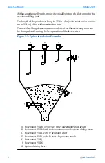
Page 6: ...switching point can be changed easily during the live operation of the level switch Figure 1 1 Typical Installation Examples A B C D E F G A Rosemount 2501R or 2501S with the rope extended fork length B Rosemount 2501M with the tube extension and optional sliding sleeve C Rosemount 2501L with the pendulum shaft D Rosemount 2501L with the boot shaped vane paddle E Rosemount 2501J F Rosemount 2501K ...

Page 7: ...ddle When a solids medium covers the vane of the paddle and causes the rotation to stop the lug is switched to the right position Figure 1 2 bottom illustration The signal output indicates a covered state due to a rising level of material and the motor is stopped until the vane becomes uncovered Figure 1 2 Switching Lug Function B A C D A Switching lug in left position uncovered state B Switching ...

Page 8: ...Selection guide Table 1 1 Rosemount 2501 Selection Guide Type of installation Model option codes 2501L 2501M 2501R 2501S 2501K 2501J Full silo detection 1 On demand detection 1 Empty silo detection 1 Vertical mounting 1 Angled mounting top 2 Horizontal mounting Angled mounting bottom 1 Consider the maximum permitted mechanical traction force 2 Available only with the bearing at tube end option Qui...

Page 9: ...2 F Dust filter for up to 302 F Bitumen Cement Wood chip dryer Pressure conveying vessel 8 bar Sugar Flour Carbon black 1 Selection varies depending on process temperature and pressure NBR Maximums are 80 C and 0 8 bar FPM Maximums are 150 C and 0 8 bar PTFE Maximums are 250 C and 0 8 bar 80 150 250 C and 5 10 bar 2 Aluminum 3 316L 1 4404 stainless steel is recommended in particular cases October ...

Page 10: ... Wiring the ac and dc voltage versions for details The universal voltage version of the level switch outputs a covered paddle or uncovered paddle status signal through DPDT relay contacts See Wiring the universal voltage version for details When using the universal voltage version of the level switch there is an adjustable delay for the switched signal output Setting a delay helps to prevent false...

Page 11: ...ions e g regular checks as part of routine inspections or establishing from a material s data sheet that it is resistant to specific chemicals 3 It is the responsibility of the installer to a Ensure the mechnical force exerted on the paddle by the bulk solids does not exceed the maximum permitted for that paddle Refer to the technical specifications in the Rosemount 2501 Product Data Sheet for fur...

Page 12: ...501L Maximum 50 Nm at 40 C Rosemount 2501M and 2501J Maximum 500 Nm at 40 C Maximum 180 Nm at 40 C Stainless steel Aluminum Rosemount 2501M and 2501K Maximum 600 Nm at 40 C Maximum 250 Nm at 40 C Stainless steel Aluminum Rosemount 2501S Contact Emerson for the maximum load of a Rosemount 2501S Quick Start Guide October 2019 12 Quick Start Guide ...

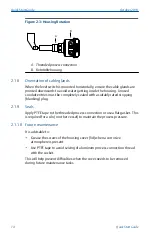
Page 13: ...sensor and could impair the protection it provides 2 1 4 Sliding sleeve Tighten both M8 screws with a torque of 20 Nm to establish a seal and maintain the process pressure See Figure 2 2 Figure 2 2 Sliding Sleeve M8 Screws A A Two off M8 screws 2 1 5 Flange mounting A suitable gasket must be fitted to provide a seal when the flanges are tightened 2 1 6 Hygienic applications The food grade material...

Page 14: ...ing plug 2 1 9 Seals Apply PTFE tape to the threaded process connection or use a flat gasket This is required for a silo or other vessel to maintain the process pressure 2 1 10 Future maintenance It is advisable to Grease the screws of the housing cover lid when a corrosive atmosphere is present Use PTFE tape to avoid seizing of aluminum process connection thread with the socket This will help pre...

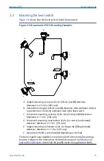
Page 15: ...ar top of silo for full silo overfill detection Maximum L 11 8 in 300 mm D Horizontal mounting near bottom of silo for control on demand detection Maximum L 5 9 in 150 mm E Angled mounting at bottom of silo for empty silo filling demand detection Maximum L 11 8 in 300 mm F A protective shield is recommended depending on the load The boot shaped vane paddle is recommended for horizontal mountings b...

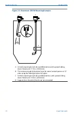
Page 16: ... L 118 in 3000 mm B The maximum angle of deviation from the normal vertical position is 10 when using the bearing at tube end option C Vertical mounting for full silo overfill detection with optional sliding sleeve Maximum L 158 in 4000 mm D Supports from the side of the silo are recommended Quick Start Guide October 2019 16 Quick Start Guide ...

Page 17: ...n with a rope extension B Demand detection with a rope extension C Empty silo filling demand detection with a rope extension Maximum L 394 in 10000 mm See Mechanical load and Sensitivity to check the limits of the rope extended vane paddle October 2019 Quick Start Guide Quick Start Guide 17 ...

Page 18: ...A Horizontal mounting for full silo overfill detection B Horizontal mounting for demand detection C Horizontal mounting for empty silo detection A protective angle is recommended depending on the load Quick Start Guide October 2019 18 Quick Start Guide ...

Page 19: ...l mounting for demand detection D Angled mounting at the bottom of silo for empty silo detection E A protective angle is recommended depending on the load The boot shaped vane paddle is recommended for horizontal mountings because it aligns to the movement of the solids material See Mechanical load and Sensitivity to check that the paddle meets the application limits October 2019 Quick Start Guide...

Page 20: ...nt on leads can cause electrical shock Ensure the power to the level switch is off and the lines to any other external power source are disconnected or not powered while wiring the level switch Ensure the wiring is suitable for the electrical current and the insulation is suitable for the voltage temperature and environment 3 2 Wiring considerations 3 2 1 Handling In cases of improper handling or ...

Page 21: ...ge of the connection terminals and the maximum current must be considered All field wiring must have insulation suitable for at least 250 Vac The temperature rating must be at least 194 F 90 C Use a shielded cable when there are electrical interferences present that are higher than stated in the EMC standards Otherwise an unshielded instrumentation cable can be used Wiring diagram The electrical c...

Page 22: ...it entries must be closed tightly with a metal stopping blanking plug 3 2 9 Micro switch protection Provide protection for micro switch contacts to protect the device against inductive load surges 3 2 10 Static charging The Rosemount 2501 must be grounded to avoid a static electrical build up This is particularly important for applications with pneumatic conveying and non metallic containers 3 2 1...

Page 23: ... W External fuse not required Note The supply voltage is selected when ordering the level switch The voltage variance of 15 includes the 10 of EN 61010 Signal output ac and dc versions Micro switched SPDT relay contacts Maximum 250 Vac 5 A non inductive Maximum 30 Vdc 4 A non inductive Figure 3 2 Terminal Connections Ac and Dc Voltage Versions 5 6 7 2 1 L N PE B A A Signal output connections B Pow...

Page 24: ...e 3 3 Wiring Connections Universal Voltage Version 6 7 10 8 9 4 5 A B 2 1 L N PE C A Signal output connections B Alarm output connections 2 C Power supply connections Maximum wire size is 4 mm2 AWG12 Grounding The PE terminal of the level switch must be connected to an earth grounding point to avoid static electrical discharges This is particularly important for applications with pneumatic conveyo...

Page 25: ...s for Fail Safe High or Low Use the FSH setting when the level switch is to be applied as a full silo detector A power failure or line break is regarded as a full silo signal as protection against overfilling Use the FSL setting when the level switch is to be applied as an empty silo detector A power failure or line break is regarded as empty silo signal as protection against running dry Figure 4 ...

Page 26: ...if necessary Fine for light material Medium for nearly every material factory setting Coarse for very sticky material The spring can be changed using small pliers Figure 4 3 Adjustment of the Spring 12 5 6 7 A B C D A Spring B Fine C Medium D Coarse Quick Start Guide October 2019 26 Quick Start Guide ...

Page 27: ...18 100 60 150 9 Boot shaped vane 35 x 106 200 12 300 18 100 60 150 9 Boot shaped vane 28 x 98 300 18 500 30 150 9 200 12 Boot shaped 26 x 77 350 21 560 33 200 12 250 15 Vane 50 x 98 300 18 500 30 150 9 250 15 Vane 50 x 150 80 4 8 120 7 2 40 2 4 60 3 6 Vane 50 x 250 30 1 8 50 3 15 0 9 25 1 5 Vane 98 x 98 100 60 150 9 50 3 75 4 5 Vane 98 x 150 30 1 8 50 3 15 0 9 25 15 Vane 98 x 250 20 1 2 30 1 8 15 ...

Page 28: ...e Electronics 5 2 Signal outputs Figure 5 1 Switching Logic Ac and Dc Versions 7 6 5 7 6 5 A B A Green B Red The dc voltage version has a LED that changes color to indicate if the paddle is covered or uncovered by solids material The ac voltage version does not have a LED Quick Start Guide October 2019 28 Quick Start Guide ...

Page 29: ...9 10 7 6 5 8 9 10 8 9 10 7 6 5 7 6 5 A B C D D C E A FSL Fail Safe Low B FSH Fail Safe High C Yellow D Green E Power failure Note See Jumper Settings for Fail Safe High or Low for details on how to select an FSH or FSL alarm output October 2019 Quick Start Guide Quick Start Guide 29 ...

Page 30: ...5 3 Switching Logic Universal Voltage Version 7 A B C 6 5 4 7 6 5 4 A Yellow or green i e no fault See Figure 5 2 B Red i e fault C LED location on PCB Figure 5 4 Connection Example 7 6 5 4 When a Rosemount 2501 is used in a full silo detection application with maximum safety the output signal can indicate Full silo signal Failure of supply voltage Incorrect wiring The level switch has developed a...

Page 31: ...observed Cleaning agent must comply with the materials of the unit chemical resistance Mainly the shaft sealing lid sealing cable gland and the surface of the unit must be considered The cleaning process must be done in a way that The cleaning agent cannot enter into the unit through the shaft sealing lid sealing or cable gland No mechanical damage of the shaft sealing lid sealing cable gland or o...

Page 32: ...6 5 Production date The production year is shown on the nameplate 6 6 Spare parts Refer to the Rosemount 2501 Product Data Sheet for all spare parts Quick Start Guide October 2019 32 Quick Start Guide ...

Page 33: ...7 Product certifications 7 1 EU Declaration of Conformity Figure 7 1 EU Declaration of Conformity Page 1 October 2019 Quick Start Guide Quick Start Guide 33 ...

Page 34: ...Figure 7 2 EU Declaration of Conformity Page 2 Quick Start Guide October 2019 34 Quick Start Guide ...

Page 35: ... diphenyl ethers PBDE 电子组件 Electronics Assembly O O O O 壳体组件 Housing Assembly O O O O O X X O O O O O 本表格系依据 SJ T11364的规定而制作 This table is proposed in accordance with the provision of SJ T11364 O 意为该部件的所有均质材料中该有害物质的含量均低于GB T 26572所规定的限量要求 O Indicate that said hazardous substance in all of the homogeneous materials for this part is below the limit requirement of GB T 26572 X 意为在该部件所使用的所有均质材料里 至少有一类...

Page 36: ...ox 1046 CH 6340 Baar Switzerland 41 0 41 768 6111 41 0 41 768 6300 RFQ RMD RCC Emerson com Asia Pacific Regional Office Emerson Automation Solutions 1 Pandan Crescent Singapore 128461 65 6777 8211 65 6777 0947 Enquiries AP Emerson com Middle East and Africa Regional Office Emerson Automation Solutions Emerson FZE P O Box 17033 Jebel Ali Free Zone South 2 Dubai United Arab Emirates 971 4 8118100 97...

Reviews: