background image

Quick Installation Guide

00825-0500-4809, Rev CA
September 2003

Threaded Flo-Tap 485 Annubar

S

TEP

 2: W

ELD

 M

OUNTING

 H

ARDWARE

NOTE

Rosemount-supplied mounting includes critical alignment hardware 
that assists in the correct drilling of the mounting hole. It also assists in 
the alignment of the sensor to the mounting hole for insertion.

1. At the pre-determined position, place the thread-o-let on the pipe, 

gap 

1

/

16

 in (1.5 mm), and place four 

1

/

4

-in. (6-mm) tack welds at 90° 

increments. 

2. Check alignment of the mounting both parallel and perpendicular to 

the axis of flow (see Figure 7). If alignment of the mounting is within 
tolerances, finish weld per local codes. If outside of specified 
tolerance, make adjustments prior to making the finish weld.

3. To avoid serious burns, allow the mounting hardware to cool 

before continuing.

Figure 7.  Alignment

(1) LMH values are as follows:

Sensor Size 1: 1.38-in. (35 mm)

Sensor Size 2: 1.56-in. (40 mm)

Sensor Size 3: 2.06-in. (52 mm)

Tack 

Welds

LMH

(1)

4809-0500 Rev CA.fm  Page 9  Monday, September 22, 2003  11:14 AM

Summary of Contents for Rosemount 485 Annubar

Page 1: ...RT Rosemount 485 Annubar Threaded Flo Tap Assembly Step 1 Location and Orientation Step 2 Weld Mounting Hardware Step 3 Install Isolation Valve Step 4 Mount Drilling Machine and Drill Hole Step 5 Remove Drilling Machine Step 6 Mount the Annubar Step 7 Insert the Annubar Step 8 Mount the Transmitter Step 9 Retracting the Annubar ...

Page 2: ...oof or instrinsically safe I S installations Refer to the 485 Annubar reference manual document number 00809 0100 4810 for more instruction This manual is also available electronically on www rosemount com If the 485 Annubar was ordered assembled to a Rosemount 3051S transmitter the new assembly is the Rosemount 3051SFA Probar Flowmeter See the following Quick Installation Guide for information on...

Page 3: ...ce temperature on all threaded connections Transmitter Temperature Sensor Connection Housing Direct Mount Electronics Connection with Valves Cage Nipple O Rings 2 Head Plate Drive Rods Threaded Pipe Fitting Guide Nipple Isolation Valve Support Plate Packing Gland Packing Follower Compression Plate Coplanar Flange with Drain Vents Transmitter and housing are shown for clarity purposes only supplied...

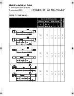
Page 4: ...straight run requirements must be met for accurate and repeatable flow measurements Refer to Table 1 for minimum pipe diameter distances from upstream disturbances Table 1 Straight Run Requirements Upstream Dimensions Downstream Dimensions Without Vanes With Vanes In Plane A Out of Plane A A C C 1 8 10 8 4 4 4 4 2 11 16 8 4 4 4 4 3 23 28 8 4 4 4 4 ...

Page 5: ... 0500 4809 Rev CA September 2003 Threaded Flo Tap 485 Annubar STEP 1 CONTINUED Upstream Dimensions Downstream Dimensions Without Vanes With Vanes In Plane A Out of Plane A A C C 4 12 12 8 4 4 4 4 5 18 18 8 4 4 4 4 6 30 30 8 4 4 4 4 ...

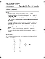
Page 6: ...lbow Out of Plane A means the bar is perpendicular to the plane of the elbow If proper lengths of straight run are not available position the mounting such that 80 of the run is upstream and 20 is downstream Use straightening vanes to reduce the required straight run length Row 6 in Table 1 applies to gate globe plug and other throttling valves that are partially opened as well as control valves M...

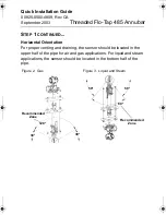
Page 7: ...l Orientation For proper venting and draining the sensor should be located in the upper half of the pipe for air and gas applications For liquid and steam applications the sensor should be located in the bottom half of the pipe Figure 2 Gas Figure 3 Liquid and Steam 30 30 120 Recommended Zone 50 50 80 Recommended Zone ...

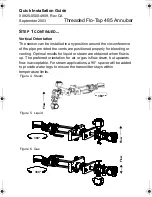
Page 8: ...ovided the vents are positioned properly for bleeding or venting Optimal results for liquid or steam are obtained when flow is up The preferred orientation for air or gas is flow down but upwards flow is acceptable For steam applications a 90 spacer will be added to provide water legs to ensure the transmitter stays within temperature limits Figure 4 Steam Figure 5 Liquid Figure 6 Gas 360 Flow 360...

Page 9: ...ad o let on the pipe gap 1 16 in 1 5 mm and place four 1 4 in 6 mm tack welds at 90 increments 2 Check alignment of the mounting both parallel and perpendicular to the axis of flow see Figure 7 If alignment of the mounting is within tolerances finish weld per local codes If outside of specified tolerance make adjustments prior to making the finish weld 3 To avoid serious burns allow the mounting h...

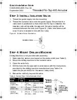
Page 10: ...vided with assembly 1 Determine the sensor size based on the probe width see Table 2 2 Mount the drilling machine to the isolation valve 3 Open the valve fully 4 Drill the hole into the pipe wall in accordance with the instructions provided by the drilling machine manufacturer use Table 2 to select the proper drill bit for the sensor being used 5 Retract the drill fully beyond the valve Table 2 Se...

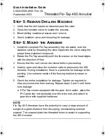
Page 11: ...ion of flow 3 Ensure that the vent valves are closed before proceeding 4 Quickly open and close the isolation valve to pressurize the 485 Annubar During installation there is a potential for leakage at the packing Use extreme caution if the flowing medium is steam or caustic 5 Check the entire installation for leakage Tighten as required to stop any connection from leaking Repeat steps 4 and 5 unt...

Page 12: ...wo turns at a time to prevent binding caused by unequal loading 3 Continue this procedure until the tip of the sensor firmly contacts the opposite side of the pipe a The orange stripes are visual indication of when the sensor is approaching the opposite side wall b As the orange strip approaches the support plate place a finger above the packing gland while cranking When movement stops the sensor ...

Page 13: ...The orange stripes are visual indication of when the sensor is approaching the opposite side wall b As the orange stripes approach the support plate remove the power drill and continue cranking manually Place a finger above the packing gland while cranking When movement stops the sensor is in contact with the opposite side wall c Turn the handle an additional 1 4 to 1 2 in to secure the sensor 3 S...

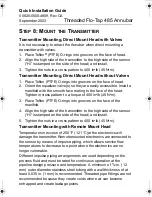
Page 14: ...b 45 N m 3 Place Teflon PTFE O rings into grooves on the face of the manifold 4 Align the high side of the transmitter to the high side of the sensor Hi is stamped on the side of the head and install 5 Tighten the nuts in a cross pattern to 400 in lb 45 N m Transmitter Mounting with Remote Mount Head Temperatures in excess of 250 F 121 C at the electronics will damage the transmitter Remote mounte...

Page 15: ...duce fluid temperature Any threaded connections should be checked after the system reaches the intended temperature because connections may come loose with contraction and expansion caused by temperature change 4 Outdoor installations for liquid saturated gas or steam may require insulation and heat tracing to prevent freezing 5 When impulse piping is longer than six feet 1 8 m the high and low im...

Page 16: ...h Pressure High and low side pressure process connections PL Primary Sensor 2 2 Low Pressure DVH Drain Vent Valve 1 Drains for gas service or vents for liquid or steam service the DP electronics chambers DVL Drain Vent Valve 2 MH Manifold 1 Isolates high side or low side pressure from the process ML Manifold 2 MEH Manifold Equalizer 1 Allows high and low pressure side access to the vent valve or f...

Page 17: ...tions Gas Service Secure the electronics above the sensor to prevent condensable liquids from collecting in the impulse piping and the DP cell Liquid Service up to 250 F 121 C Secure the electronics below the sensor to ensure that air will not be introduced into the impulse piping or the electronics Figure 12 Gas Figure 13 Liquid ...

Page 18: ...UED Steam or Liquid Service above 250 F 121 C Mount the electronics below the process piping adjust 10 to 15 degree above direct vertical down Route the impulse piping down to the electronics and fill the system with cool water through the two tee fittings Figure 14 Horizontal Line Figure 15 Vertical Line ...

Page 19: ...packing body mechanism PRODUCT CERTIFICATION Approved Manufacturing Locations Rosemount Inc Chanhassen Minnesota USA European Directive Information The EC declaration of conformity for all applicable European directives for this product can be found on the Rosemount website at www rosemount com A hard copy may be obtained by contacting our local sales office European Pressure Equipment Directive P...

Page 20: ...Quick Installation Guide 00825 0500 4809 Rev CA September 2003 Threaded Flo Tap 485 Annubar ...

Reviews: