background image

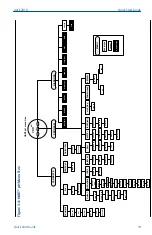
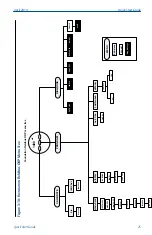
Figure 3-4: HART

®

 pH Menu Tree

7.00

 pH

CALIBRA

TE

PROGRAM

DIAGNOSE

CALIbrAtE

Std

tEMP AdJ

OUtPUt CAL

CAL bF1

bF 1

bF1 4.01

CAL bF2

bF2

bF2 10.01

Std 7.00

SLOPE 

59.01

tEMP 25.0

Cur 4.00

Cur 20.00

OutPut

dIAGnOStiC

tEMP

dISPL

A

Y

HArt

bUFFEr

ISOPOtnAL

LinE 

FrEq

P

AMP=trAnS

dEF

AULt

4 MA 00.00

20 MA 14.00

HoLd 21.00

FAULt 22.00

dPn 0.00

tESt 12.00

ROFFSt 

000

dIAG OFF

iMpiC ON

GFH 1500

GWH 1000

GWL 

020

GFL 

010

CAL 000

rEF LO

rFH 140

rWH 040

rWL 000

rFL 000

tAUT

O On

tMAN 25.0

tYPE PM

tEMP C

OUtPUt Cur

COdE 000

AddrESS 00

PrEAMp 02

burSt OFF

Id 0

bAUT

O On

bUFFEr Gnd

StAbiLiSE

UNE 10

deLtA 00.02

tCOEF 00.00

ISO 

07.00

Snr 07.00

LinE 

00

FACtOrY

nO

YES

InPut 

58.9

SLOPE

OFFSt

GIMP 

1000

rIMP 10

5081-P-Ht

SoFt

FAULtS

nonE

MENU

Sub-menu

PROMPT

Diag Message

HArd

HART pH menu tree

April 2019

Quick Start Guide

Quick Start Guide

19

Summary of Contents for Rosemount 5081

Page 1: ...Quick Start Guide 00825 0100 3581 Rev AA April 2019 Rosemount 5081 Explosion Proof Single Input Intelligent Transmitter ...

Page 2: ...rized parts and procedures can affect the product s performance place the safe operation of your process at risk and VOID YOUR WARRANTY Look alike substitutions may result in fire electrical hazards or improper operation Ensure that all equipment doors are closed and protective covers are in place except when maintenance is being performed by qualified people to prevent electrical shock and person...

Page 3: ...er representative All costs of dismantling reinstallation and freight and the time and expenses of Seller s personnel for site travel and diagnosis under this warranty clause shall be borne by Buyer unless accepted in writing by Seller Goods repaired and parts replaced during the warranty period shall be in warranty for the remainder of the original warranty period or ninety 90 days whichever is l...

Page 4: ...Quick Start Guide April 2019 4 Emerson com Rosemount ...

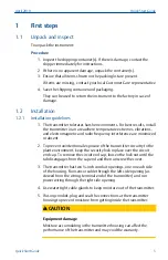
Page 5: ...e minimized or absent 2 To prevent unintentional exposure of the transmitter circuitry to the plant environment keep the security lock in place over the circuit end cap To remove the circuit end cap loosen the lock nut until the tab disengages from the cap end and then unscrew the cover 3 The transmitter has two inch conduit openings one on each side of the housing Run sensor cable through the lef...

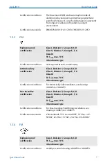
Page 6: ...rclockwise into the desired position 4 Position the display board on the stand offs Replace and tighten the bolts 5 Replace the circuit end cap 1 3 Hazardous area certifications 1 3 1 IECEx Certificate IECEx BAS 9 0159X Intrinsically safe marking Ex ia IIC T4 Ga 20 C Tamb 65 C Certification conditions The Rosemount 5081 enclosure may be made of aluminum alloy and given a protective polyurethane pa...

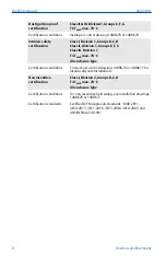
Page 7: ... 1 Groups B C D Class II Division 1 Groups E F G Class III T4 Tamb max 70 C 4X enclosure type Certification conditions For Intrinisically Safe installation see drawings 1400674 or 1400675 Non incendive certification Class I Division 2 Groups B C D Class II Division 2 Groups E F G Class III T4 Tamb max 70 C 4X enclosure type Certification conditions For Non Incendive Field Wiring installation see d...

Page 8: ...osure type Certification conditions Connect per control drawings 1400676 or 1400677 for Intrinsically Safe Installations Non incendive certification Class I Division 2 Groups B C D T4 Tamb max 70 C 4X enclosure type Certification conditions For non incendive field wiring see installation drawings 1400676 or 1400677 Certification standards Certified to FM Approvals standards 3600 2011 3610 2015 361...

Page 9: ... Power supply overview The tables below display the minimum and maximum voltages needed to operate the Rosemount 5081 Minimum supply voltage at the transmitter terminals 12 0 Vdc Minimum power supply for load resister 250 Ohms Maximum power supply voltage 42 0 Vdc Maximum power supply voltage for intrinsically safe installations 30 0 Vdc April 2019 Quick Start Guide Quick Start Guide 9 ...

Page 10: ...ply voltage needed to provide 12 Vdc at the transmitter terminals for a 22 mA current Lower line Power supply voltage needed to provide 30 Vdc for a 22 mA current Maximum current About 24 mA Minimum load for digital communications 250 Ohms Minimum power supply voltage to supply the 12 0 Vdc lift off voltage at the transmitter 17 5 Vdc Quick Start Guide April 2019 10 Emerson com Rosemount ...

Page 11: ...mitter to earth ground Note For optimum EMI RFI immunity shield the power supply output cable and enclose it in an earth grounded metal conduit Do not run power supply signal wiring in the same conduit or cable tray with AC power lines or with relay actuated signal cables Keep power supply signal wiring at least 6 ft 2 m away from heavy electrical equipment An additional 0 1 mA current loop is ava...

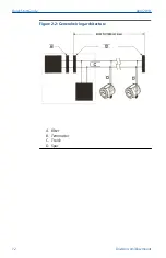
Page 12: ...Figure 2 2 General wiring architecture A Filter B Terminator C Trunk D Spur Quick Start Guide April 2019 12 Emerson com Rosemount ...

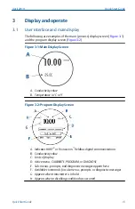
Page 13: ...or F Figure 3 2 Program Display Screen A Indicates HART or FOUNDATION Fieldbus digital communiciations B Conductivity value C Units of display D Active menu CALIBRATE PROGRAM or DIAGNOSE E Sub menus prompts and diagnostic messages appear here F Available commands for sub menus prompts or diagnostic messages G Appears when transmitter is in hold H Appears when a disabling condition has occurred Apr...

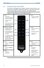
Page 14: ...default settings 6 HOLD Access to turn hold readings on or off 2 Editing arrow keys Change values of a flashing display Left and right arrows move the cursor by one digit Up and down arrows increase or decrease the values and navigate through the display options 7 ENTER Advance to the next prompt Store selected item Store value in memory 3 CAL Access to Calibration menu 8 NEXT Advance to the next ...

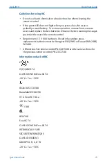
Page 15: ...batteries If used in hazardous areas replacement batteries must be Energizer E92 EN92 or Duracell MN2400 PC2400 All functions for remote control PN 24479 00 are the same as those for the previous remote control PN 23572 00 Information on back of IRC IS I 1 ABCD T4 CLASS I ZONE 0 AEx ia IIC T4 20 C Ta 50 C IECEx BAS 13 0108 Baseefa02ATEX0198 II 1 G Ex ia IIC T4 Ga 20 C Ta 50 C 1180 LR34186 Ex ia II...

Page 16: ...VERTISSEMENT LA SUBSTITUTION DE COMPOSANTS PEUT COMPROMETTRE LA SÉCURITÉ INTRINSÈQUE POUR PREVENIR L INFLAMMATION D ATMOSPHERE NE CHANGER LES BATTERIES QUE DANS DES EMPLACEMENTS DESIGNES NON DANGEREUX USE ONLY ENERGIZER E92 EN92 OR DURACELL MN2400 PC2400 2 1 5 V AAA BATTERIES Quick Start Guide April 2019 16 Emerson com Rosemount ...

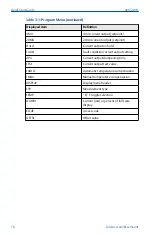
Page 17: ...alibrate Program and Diagnose Calibrate and Program menus have additional sub menus as shown in the figures below Table 3 1 Program Menu Displayed item Definition OUtpUt Current output menu header April 2019 Quick Start Guide Quick Start Guide 17 ...

Page 18: ...urrent output setting dPn Current output dampening time tESt Current output test value tAUtO Automatic temperature compensation tMAn Manual temperature compensation dISPLAY Display menu header tYP Measurement type tEMP C F toggle selection OUtPUt Current mA or percent of full scale display COdE Access code OFFSt Offset value Quick Start Guide April 2019 18 Emerson com Rosemount ...

Page 19: ...FAULt 22 00 dPn 0 00 tESt 12 00 ROFFSt 000 dIAG OFF iMpiC ON GFH 1500 GWH 1000 GWL 020 GFL 010 CAL 000 rEF LO rFH 140 rWH 040 rWL 000 rFL 000 tAUTO On tMAN 25 0 tYPE PM tEMP C OUtPUt Cur COdE 000 AddrESS 00 PrEAMp 02 burSt OFF Id 0 bAUTO On bUFFEr Gnd StAbiLiSE UNE 10 deLtA 00 02 tCOEF 00 00 ISO 07 00 Snr 07 00 LinE 00 FACtOrY nO YES InPut 58 9 SLOPE OFFSt GIMP 1000 rIMP 10 5081 P Ht SoFt FAULtS n...

Page 20: ...ULt 22 00 dPn 0 00 tESt 12 00 ROFFSt 000 dIAG OFF iMpiC ON GFH 1500 GWH 1000 GWL 020 GFL 010 CAL 000 rEF LO rFH 140 rWH 040 rWL 000 rFL 010 tAUTO On tMAN 25 0 tYPE PH tEMP C OUtPUt Cur COdE 010 AddrESS 00 PrEAMp 02 burSt OFF Id 0 bAUTO On bUFFEr Gnd StAbiLiSE UNE 10 deLtA 00 02 tCOEF 00 00 ISO 07 00 Snr 07 00 LinE 00 FACtOrY nO YES InPut 58 9 SLOPE OFFSt GIMP 1000 rIMP 10 5081 P Ht SoFt FAULtS non...

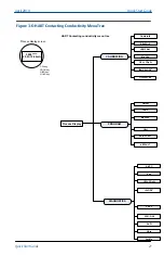
Page 21: ...ROG key DIAG key HOLD key Process Display CALIBRATION PROGRAM DIAGNOSTICS CALIbrAtE SEnSOr 0 tEMP AdJ CELL COnSt tEMP SLOPE1 OUtPUt CAL OutPut tEMP dISPLAY HArt SEtUP CuST dEFAULT AbS C 0 air CELL COnSt tSLOPE1 CAL F 5081 C Ht SoFt HArd FaULTs Process display screen Mtr CAL April 2019 Quick Start Guide Quick Start Guide 21 ...

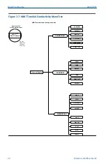
Page 22: ... DIAG key HOLD key Process Display CALIBRATION PROGRAM DIAGNOSTICS CALIbrAtE SEnSOr 0 tEMP AdJ CELL COnSt tEMP SLOPE OUtPUt CAL OutPut tEMP dISPLAY HArt SEtUP CuST dEFAULT AbS C OFFSt CELL COnSt tSLOPE1 CAL F 5081 T Ht SoFt HArd FaULTs Model 5081T HT Process Display Screen Quick Start Guide April 2019 22 Emerson com Rosemount ...

Page 23: ...play type Unit ppm sensor ADO Unit ppm temp C Output Cur Code 000 if O 2 If Cl free and total If O 3 FACTORY NO span Cal 0 Cal stabilize limit 00 05 time 10 SlOpe snGl Salnty 00 0 All if chlorine if O 2 Line 60 PH Pamp trans Man 7 00 diaGnostiC roffst 060 diaG OFF lmptC On GFI 1500 GFL 000 pH Cal baUtO On bUFFEr Std StAbILISE tIME 00 dELtA 0 02 Cl only if On if Off Enter Next Unit nnHG pman 760 ty...

Page 24: ... 060 dIAG OFF iMpiC ON GFH 1500 GWH 1000 GWL 020 GFL 010 CAL 000 rEF LO rFH 140 rWH 040 rWL 000 rFL 000 tAUTO On tMAN 25 0 tYPE PH tEMP C OUtPUt Cur COdE 000 bAUTO On bUFFEr Std StAbiLiSE tIME 10 deLtA 00 02 tCOEF 00 00 ISO 07 00 Snr 07 00 LinE 60 FACtOrY NO YES InPut 58 9 SLOPE OFFSt GIMP 1000 rIMP 10 5081 P Ht SoFt FAULtS nonE MENU Sub menu PROMPT Diag Message HArd Foundation Fieldbus pH menu tr...

Page 25: ... LinE FrEq PAMP trAnS dEFAULt rOFFSt 060 dIAG OFF iMpiC OFF rEF LO rFH 140 rWH 040 rWL 000 rFL 000 tYPE ORP tEMP C OUtPUt Cur COdE 000 LinE 60 FACtOrY nO YES OFFSt 120 rIMP 10 5081 P FF SoFt 00 02 FAULtS nonE MENU Sub menu PROMPT Diag Message Hard 01 Foundation Fieldbus ORP menu tree April 2019 Quick Start Guide Quick Start Guide 25 ...

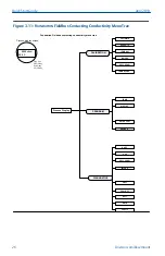
Page 26: ...ty menu tree CAL key PROG key DIAG key HOLD key Process Display CALIBRATION PROGRAM DIAGNOSTICS CALIbrAtE SEnSOr 0 tEMP AdJ Mtr CAL CELL COnSt tEMP SLOPE1 tEMP dISPLAY SEtUP CuST dEFAULT AbS C 0 air CELL COnSt tSLOPE1 CAL F 5081 C FF SoFt HArd FaULTs Process display screen Quick Start Guide April 2019 26 Emerson com Rosemount ...

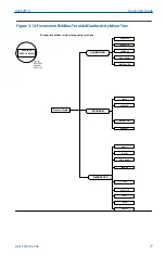
Page 27: ... toroidal conductivity menu tree CAL key PROG key DIAG key HOLD key Process Display CALIBRATION PROGRAM DIAGNOSTICS CALIbrAtE SEnSOr 0 tEMP AdJ CELL COnSt tEMP SLOPE tEMP dISPLAY SEtUP CuST dEFAULT AbS C OFFSt CELL COnSt tSLOPE CAL F 5081 T FF SoFt HArd FaULTs April 2019 Quick Start Guide Quick Start Guide 27 ...

Page 28: ...enu tree temp DEFAULT Cal setup Line freq bar press taUto On tman 25 0 display type Unit ppm sensor stnd Unit ppm temp C Output Cur Code 000 if O 2 If Cl free and total If O 3 FACTORY NO span Cal 0 Cal stabilize limit 00 05 time 10 SlOpe snGl Salnty 00 0 All if chlorine if O 2 Line 60 PH Pamp trans Man 7 00 diaGnostiC roffst 060 diaG OFF lmptC On GFI 1500 GFL 000 pH Cal baUtO On bUFFEr Std StAbILI...

Page 29: ...sius and Fahrenheit 4 Press ENTER and then RESET 5 Press PROG NEXT and ENTER in this order 6 Use the arrow keys to toggle T AUTO between ON or OFF This determines whether the transmitter uses the process temperature ON or a manual temperature OFF 7 Press ENTER 8 If you select OFF enter the manual temperature desired using the arrow keys 9 Press ENTER April 2019 Quick Start Guide Quick Start Guide ...

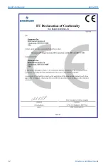
Page 30: ...ing pages are the EU Declarations of Conformity for the Rosemount 5081 C Contacting Conductivity Transmitter 5081 P A Amperometric pH Transmitter and 5081 T Toroidal Conductivity Transmitter Quick Start Guide April 2019 30 Emerson com Rosemount ...

Page 31: ...April 2019 Quick Start Guide Quick Start Guide 31 ...

Page 32: ...Quick Start Guide April 2019 32 Emerson com Rosemount ...

Page 33: ...April 2019 Quick Start Guide Quick Start Guide 33 ...

Page 34: ...Quick Start Guide April 2019 34 Emerson com Rosemount ...

Page 35: ...April 2019 Quick Start Guide Quick Start Guide 35 ...

Page 36: ...B China RoHS Table Quick Start Guide April 2019 36 Emerson com Rosemount ...

Page 37: ...April 2019 Quick Start Guide Quick Start Guide 37 ...

Page 38: ...Quick Start Guide April 2019 38 Emerson com Rosemount ...

Page 39: ...April 2019 Quick Start Guide Quick Start Guide 39 ...

Page 40: ... Box 1046 CH 6340 Baar Switzerland T 41 0 41 768 6111 F 41 0 41 768 6300 liquid csc emerson com MIDDLE EAST AND AFRICA Emerson Automation Solutions Emerson FZE Jebel Ali Free Zone Dubai United Arab Emirates P O Box 17033 T 971 4 811 8100 F 971 4 886 5465 liquid csc emerson com Linkedin com company Emerson Automation Solutions twitter com rosemount_news Facebook com Rosemount youtube com RosemountM...

Reviews: