Reference Manual
00809-0100-4882, Rev AB
May 2019
Rosemount 5081FG
2-4
Installing Oxygen Probe
1. Ensure all components are available to install the probe.
NOTE
Leave the probe inner protective cover in place until installation. This is
required to protect the ceramic cell during movement.
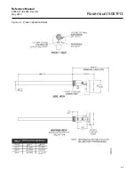
2. If using an optional adapter plate (Figure 2-2) or an optional mounting
flange (Figure 2-3), weld or bolt the component onto the duct. The
through hole in the stack or duct wall and refractory material must be
2 in. (50,8 mm) diameter, minimum.
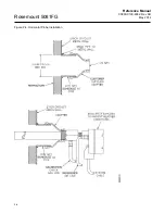
3. If the optional adapter plates are not used, a 2 in. NPT, schedule 40,
pipe nipple (Figure 2-4) should be welded to the stack or duct wall.
When a 2 in. NPT to 1.25 NPT adapter is threaded to the welded pipe
nipple, the adapter provides the pipe threads needed for the probe's
process fitting.
4. Where high particulate or slag is in the flue gas stream, it may be
desirable to inset the probe in the refractory as shown in Figure 2-5. Use
pipe couplings and nipples to adjust the probe insertion depth.
5. Use high temperature material (alumina wool) to seal around the probe
during insertion. This prevents hot gases from escaping or cold air from
entering the stack or duct.
6. Initially insert the probe to a depth of 3 in. (76,2 mm) or 1/2 the depth of
the stack or duct refractory, whichever is greater.
7. After initial insertion, insert the probe at a rate of 1 in. (25,4 mm) per
minute until the probe is fully inserted.
8. Install anti-seize compound on the pipe threads and screw the probe
into the process flange or adapter.
9. If insulation was removed to access the duct work for probe mounting,
make sure the insulation is replaced. See Figure 2-4.
The probe was specially packaged to prevent breakage due to handling. Do not remove the
padding material from the probe until immediately before installation.
After initial insertion, do not insert the probe at a rate exceeding 1 in. per minute (25.4 mm
per minute) or damage to the probe may result due to thermal shock.
If the ducts will be washed down during outage, MAKE SURE to power down the probes
and remove them from the wash area.
Summary of Contents for Rosemount 5081FG
Page 2: ......
Page 6: ...Reference Manual 00809 0100 4882 Rev AB June 2019 Rosemount 5081FG TOC 4 ...
Page 20: ...Reference Manual 00809 0100 4882 Rev AB May 2019 Rosemount 5081FG 1 10 ...
Page 36: ...Reference Manual 00809 0100 4882 Rev AB May 2019 Rosemount 5081FG 2 16 ...
Page 53: ...Reference Manual 00809 0100 4882 Rev AB May 2019 Rosemount 5081FG 3 17 Figure 3 20 Show Fault ...
Page 82: ...Reference Manual 00809 0100 4882 Rev AB May 2019 Rosemount 5081FG 6 6 ...
Page 94: ...Reference Manual 00809 0100 4882 Rev AB May 2019 Rosemount 5081FG A 8 ...
Page 96: ...Reference Manual 00809 0100 4882 Rev AB June 2019 Rosemount 5081FG B 2 ...
Page 98: ...Reference Manual 00809 0100 4882 Rev AB June 2019 Rosemount 5081FG B 2 ...
Page 100: ......
Page 103: ...Index 2 ...


