Reference Manual
00809-0100-4882, Rev AB
May 2019
Rosemount 5081FG
4-3
Method 2, For Load Resistance < 250 ohms
Refer to Figure 4-2 and the following steps to connect the field communicator
to a signal line with < 250 ohms load resistance.
1. At a convenient point break the analog output 4-20 mA signal line and
install the optional 250 ohm load resistor.
2. Plug the load resistor into the rear panel of the field communicator.
Figure 4-2. Signal Line Connections, < 250 Ohms Load Resistance
Explosions can result in death or serious injury. Do not make connections to the field
communicator's serial port, 4-20 mA signal line, or NiCad recharger jack in an explosive
atmosphere.
Summary of Contents for Rosemount 5081FG
Page 2: ......
Page 6: ...Reference Manual 00809 0100 4882 Rev AB June 2019 Rosemount 5081FG TOC 4 ...
Page 20: ...Reference Manual 00809 0100 4882 Rev AB May 2019 Rosemount 5081FG 1 10 ...
Page 36: ...Reference Manual 00809 0100 4882 Rev AB May 2019 Rosemount 5081FG 2 16 ...
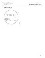
Page 53: ...Reference Manual 00809 0100 4882 Rev AB May 2019 Rosemount 5081FG 3 17 Figure 3 20 Show Fault ...
Page 82: ...Reference Manual 00809 0100 4882 Rev AB May 2019 Rosemount 5081FG 6 6 ...
Page 94: ...Reference Manual 00809 0100 4882 Rev AB May 2019 Rosemount 5081FG A 8 ...
Page 96: ...Reference Manual 00809 0100 4882 Rev AB June 2019 Rosemount 5081FG B 2 ...
Page 98: ...Reference Manual 00809 0100 4882 Rev AB June 2019 Rosemount 5081FG B 2 ...
Page 100: ......
Page 103: ...Index 2 ...


