1
Manual Supplement
00809-0300-4570, Rev BA
Rosemount 5708 Series 3D Solids Scanner Integration with DeltaV
2016
Rosemount 5708 Series 3D Solids Scanner Integration with DeltaV
Rosemount
™
5708 Series 3D Solids Scanner
Integration with DeltaV
™
Introduction . . . . . . . . . . . . . . . . . . . . . . . . . . . . . . . . . . . . . . . . . . . . . . . . . . . . . . . . . . . . . .page 1
Specifications . . . . . . . . . . . . . . . . . . . . . . . . . . . . . . . . . . . . . . . . . . . . . . . . . . . . . . . . . . . . . page 2
Network setup . . . . . . . . . . . . . . . . . . . . . . . . . . . . . . . . . . . . . . . . . . . . . . . . . . . . . . . . . . . . page 3
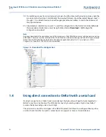
Using direct connection to DeltaV with a serial card . . . . . . . . . . . . . . . . . . . . . . . . . . . . page 14
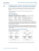
Configuring byte order for connection via serial card . . . . . . . . . . . . . . . . . . . . . . . . . . . page 15
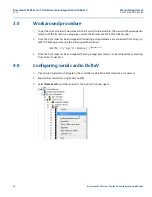
Workaround procedure . . . . . . . . . . . . . . . . . . . . . . . . . . . . . . . . . . . . . . . . . . . . . . . . . . . . . page 16
Configuring serial card in DeltaV . . . . . . . . . . . . . . . . . . . . . . . . . . . . . . . . . . . . . . . . . . . . . page 16
Configuring control strategies to obtain correct process values . . . . . . . . . . . . . . . . . . page 23
Setting up 3DVison in DeltaV operate screen . . . . . . . . . . . . . . . . . . . . . . . . . . . . . . . . . .page 27
1.0
Introduction
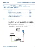
This document indicates how to setup and configure Rosemount 5708 3D Solids Scanner with DeltaV
using two different methods. Configuration details are included for the physical network, DeltaV
Explorer, 3DMultiVision
™
Client, and VIMNet. The VIMNet application interfaces with the VIM card - a
necessary component for one of the setups which DeltaV communicates with the 3DMultiVision server
through. DeltaV Explorer configuration is performed on the DeltaV ProPlus Station; 3DMultiVision and
VIMNet configuration is performed on an application station.
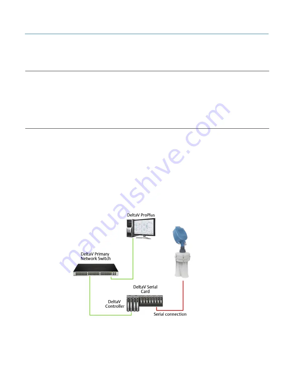
1.
The scanner is directly connected to DeltaV Serial Card. Using the 3DMultiVision software to view
3D images 3D image from the scanner is not possible in direct connection.


