Rosemount LinkPro Operating Instructions
November 2017
Reference Manual
00809-0100-4570, Rev DA
Rosemount LinkPro Operating Instructions
170
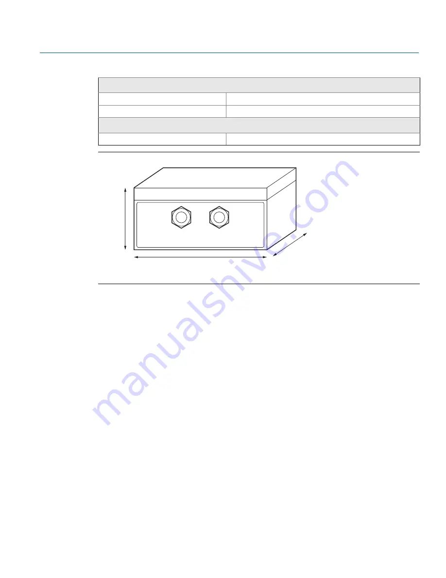
Figure D-3. Product Dimensions
Dimensions are in inches (mm).
D.4
Mounting
This chapter provides information on mounting the Rosemount LinkPro.
D.4.1
Position
Select an easy-to-reach position for mounting and connecting. Wiring instructions are located on a label
inside the unit’s front cover.
Mount the instrument to ensure optimum GSM reception. Do not mount in a closed metallic
box/rack/container. Since the antenna was designed to be internal, the Rosemount LinkPro housing is
made of plastic to enable maximal reception.
D.4.2
Moisture
Use the recommended cables (see
Selecting connection cable page 173
) and tighten the cable gland to
protect the instrument from moisture and penetration of water.
Lead the connection cable downward in front of the cable entry for additional protection. Rain and
condensation water can thus drain off naturally without affecting the connection.
D.4.3
Wall mounting
To mount the Rosemount LinkPro on the wall:
1.
Mark the holes in accordance with the following drilling template.
Radio
Spurious emissions
EN 301 511 V9.0.2
FCC approval
FCC 47 CFR part15:2007, subpart B, class A
Electromechanical data
Cable entry/plug
2
⫻
cable gland M20
x
1.5 (cable ø 8mm to13mm)
Table D-2. Rosemount LinkPro Technical Specifications
3.5
(90)
10 (255)
7 (180)
Summary of Contents for Rosemount 5708
Page 1: ...Reference Manual 00809 0100 4570 Rev DA November 2017 Rosemount 5708 3D Solids Scanner ...
Page 2: ...ii Section Title November 2017 Reference Manual 00809 0100 4570 Rev DA ...
Page 8: ...vi Reference Manual 00809 0100 4570 Rev DA Contents November 2017 Contents ...
Page 12: ...2 Reference Manual 00809 0100 4570 Rev DA Introduction November 2017 Introduction ...
Page 202: ...ii Reference Manual 00809 0100 4570 Rev DA Index November 2017 Index ...
Page 203: ...iii Reference Manual 00809 0100 4570 Rev DA November 2017 ...


