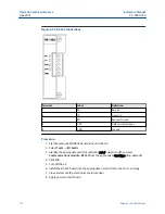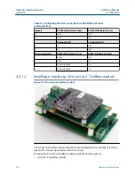
•
A F
OUNDATION
Fieldbus assembly bracket
•
A F
OUNDATION
Fieldbus cable assembly
•
Two screws
•
Two flat washers
Remove a F
OUNDATION
™
Fieldbus module
Note
Be sure to properly ground yourself before performing this procedure.
Procedure
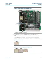
1. Unscrew the two local operator interface (LOI) post tips.
You can now detach the F
OUNDATION
Fieldbus module from the card cage.
2. Remove the two screws that attach the F
OUNDATION
Fieldbus assembly bracket to
the F
OUNDATION
Fieldbus module.
Install a F
OUNDATION
™
Fieldbus module
NOTICE
Properly ground yourself before performing this procedure.
Note
The gas chromatograph (GC) draws 21 mA from the F
OUNDATION
Fieldbus module.
Procedure
1. Attach the Fieldbus assembly bracket to the F
OUNDATION
Fieldbus module by
aligning the two holes in the Fieldbus assembly bracket with the two holes at the
bottom of the F
OUNDATION
Fieldbus module and screwing in the two thumb screws.
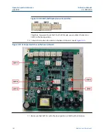
2. Attach the Fieldbus assembly bracket to the card cage by aligning the Fieldbus
assembly bracket's second set of holes with the local operator interface (LOI) post
tip holes in the card cage.
3. Screw in the LOI post tips.
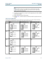
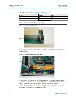
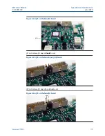
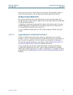
4. Use the
OUNDATION
Fieldbus cable assembly to the
backplane:
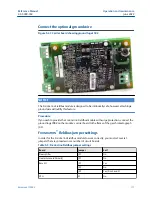
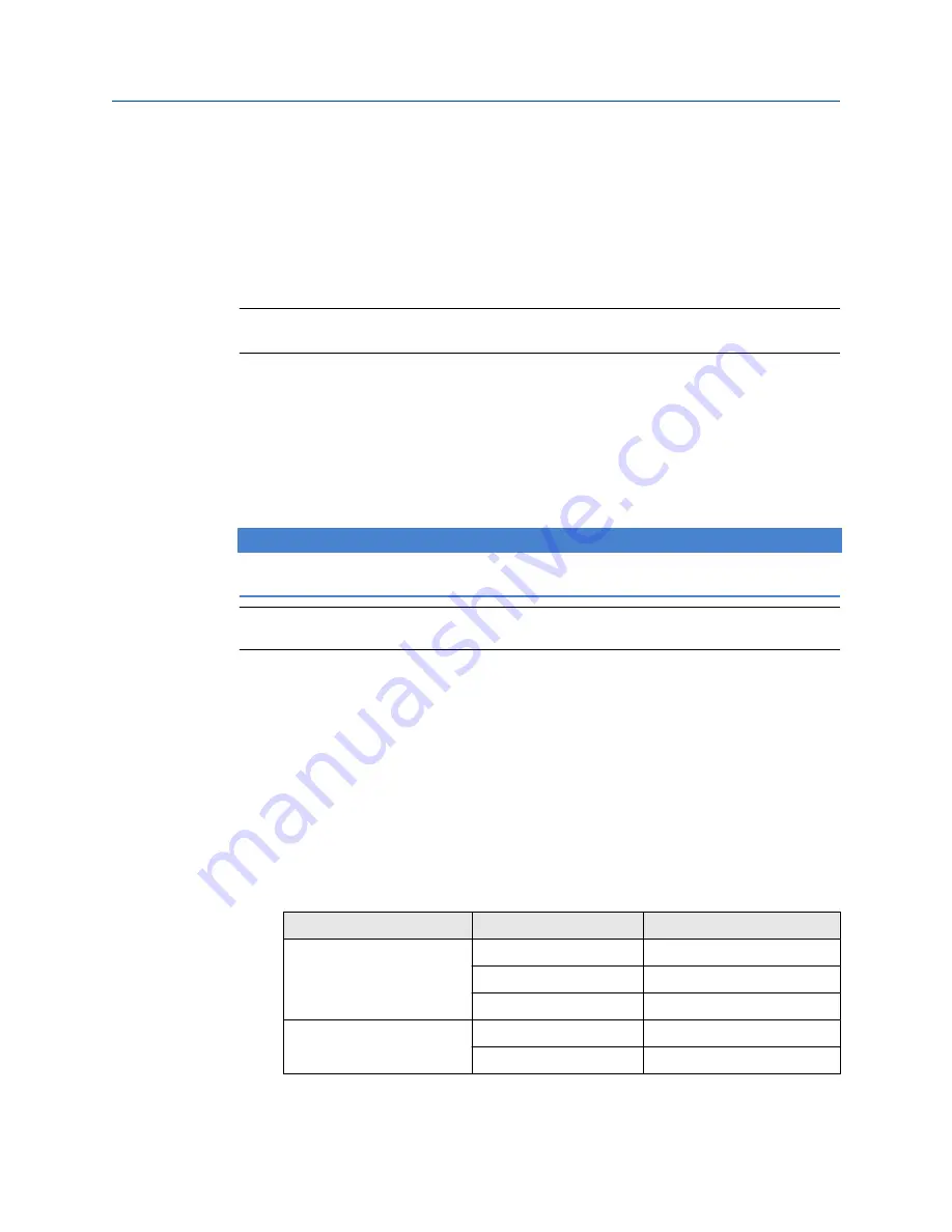
Table 5-4: F
OUNDATION
Fieldbus wiring
Backplane terminal block
Post number
Wire color
TB15
1
Brown
2
White
3
Green
TB13
3
Red
4
Black
Reference Manual
Operation and maintenance
2-3-9000-744
June 2022
Rosemount 700XA
175
Summary of Contents for Rosemount 700XA
Page 1: ...Reference Manual 2 3 9000 744 Rev L June 2022 Rosemount 700XA Gas Chromatograph ...
Page 6: ...TxD TD or Sout Transmit data or signal out 6 ...
Page 30: ...Overview Reference Manual June 2022 2 3 9000 744 30 Emerson com Rosemount ...
Page 100: ...Installation and start up Reference Manual June 2022 2 3 9000 744 100 Emerson com Rosemount ...
Page 182: ...Operation and maintenance Reference Manual June 2022 2 3 9000 744 182 Emerson com Rosemount ...
Page 280: ......
Page 281: ......
Page 282: ......
Page 293: ......

