Instruction Manual
IM-105-4000, Rev 1.3
October 2008
OPM 4000
2-18
BEAM ALIGNMENT
PROCEDURE
NOTE
Alignment can not be done unless the power is applied to the stack mounted
service module. The control unit does not have to be connected or powered to
perform an alignment. For optimal alignment accuracy the stack should be at
normal operating temperature. Alignment should be completed before
instrument calibration.
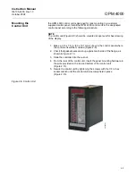
Service module switches (Figure 2-14) should be in the normal operating
positions given below.
• Operate/Zero - Operate
• Operate/Span - Operate
• Normal/Test - Normal
• Opacity/T
2
- Opacity
Figure 2-14. Service Module
Switch Location
OPERATE
SPAN
ZERO
EXTERNAL
METER (mA)
NORMAL
TEST
OPACITY
T
2
0 100%
00.3
38450005
Model:
Serial:
Summary of Contents for Rosemount Analytical OPM 4000
Page 2: ......
Page 6: ......
Page 10: ...Instruction Manual IM 105 4000 Rev 1 3 October 2008 OPM 4000 TOC 4 ...
Page 14: ...Instruction Manual IM 105 4000 Rev 1 3 October 2008 OPM 4000 iv ...
Page 42: ...Instruction Manual IM 105 4000 Rev 1 3 October 2008 OPM 4000 2 20 ...
Page 52: ...Instruction Manual IM 105 4000 Rev 1 3 October 2008 OPM 4000 4 6 ...
Page 58: ...Instruction Manual IM 105 4000 Rev 1 3 October 2008 OPM 4000 5 6 ...
Page 64: ...Instruction Manual IM 105 4000 Rev 1 3 October 2008 OPM 4000 6 6 ...
Page 100: ...Instruction Manual IM 105 4000 Rev 1 3 October 2008 OPM 4000 A 24 ...
Page 102: ...Instruction Manual IM 105 4000 Rev 1 3 October 2008 OPM 4000 B 2 ...
Page 104: ...Instruction Manual IM 105 4000 Rev 1 3 October 2008 OPM 4000 C 2 ...
Page 114: ...Instruction Manual IM 105 4000 Rev 1 3 October 2008 OPM 4000 D 10 ...
Page 116: ...Instruction Manual IM 105 4000 Rev 1 3 October 2008 Index 2 OPM 4000 ...


