


Hardware Preparation and Installation
RTM-ATCA-F140 Installation and Use (6806800M97A)
29
2. Wait until the front board blue LED is illuminated permanently.
3. Remove face plate cables, if applicable.
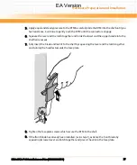
4. Unfasten the screws of the RTM face plate until the RTM is detached from the shelf.
5. Unlatch the RTM upper and lower handles and rotate fully outward.
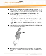
6.
Remove the blade from the shelf.
If the LED continues to blink, a possible reason may be that upper layer software rejects the
blade extraction request
EA Version
Summary of Contents for RTM-ATCA-F140
Page 6: ...RTM ATCA F140 Installation and Use 6806800M97A Contents 6 Contents Contents EA Version ...
Page 8: ...RTM ATCA F140 Installation and Use 6806800M97A 8 List of Tables EA Version ...
Page 10: ...RTM ATCA F140 Installation and Use 6806800M97A 10 List of Figures EA Version ...
Page 20: ...Introduction RTM ATCA F140 Installation and Use 6806800M97A 20 EA Version ...
Page 34: ...Controls LEDs and Connectors RTM ATCA F140 Installation and Use 6806800M97A 34 EA Version ...
Page 58: ...Functional Description RTM ATCA F140 Installation and Use 6806800M97A 58 EA Version ...
Page 60: ...Related Documentation RTM ATCA F140 Installation and Use 6806800M97A 60 EA Version ...
Page 70: ...Index RTM ATCA F140 Installation and Use 6806800M97A 70 EA Version ...
Page 71: ...EA Version ...


