Hardware Reference Manual
Hardware Interface
GFK-3022E
September 2021
Hardware Interface
39
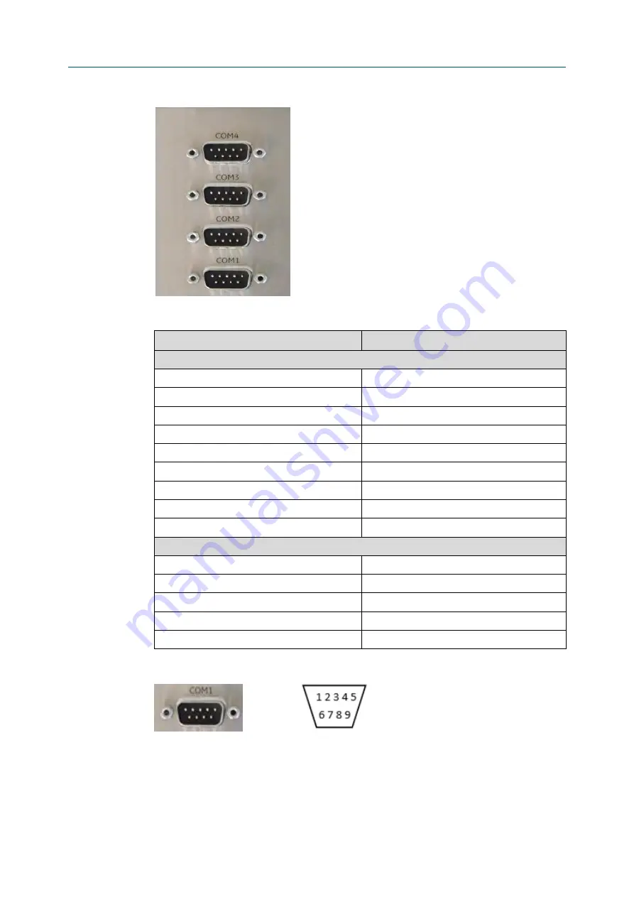
Figure 5-12
Serial Ports
–
4-Slot Variant
Table 5-9
Serial Ports
Signal Name
Pin
RS
–
232 Pin
DCD
1
RxD
2
TxD
3
DTR
4
GND
5
DSR
6
RTS
7
CTS
8
RI
9
RS
–
422 / RS
–
485 Pin
Rx+
1
Rx-
2
Tx-
3
Tx+
4
GND
5
Figure 5-13
Pin Assignment
For RS
–
422 and RS
–
485-4 wire modes, connect the corresponding RX+/- with the TX+/- of the
counterpart and vice versa. For RS
–
485-2 wire mode connect RX+ and TX+ together with the +
line of the cable and the RX- and the TX- together with the
–
line of the cable.


