background image

Quick Installation Guide

00825-0100-4420, Rev DA
July 2009

1420 Wireless Gateway

15

P

RODUCT

 C

ERTIFICATIONS

Approved Manufacturing Locations

Rosemount Inc. – Chanhassen, Minnesota, USA

Telecommunication Compliance

All wireless devices require certification to ensure that they adhere to regulations regarding 
the use of the RF spectrum. Nearly every country requires this type of product certification. 
Emerson is working with governmental agencies around the world to supply fully compliant 
products and remove the risk of violating country directives or laws governing wireless 
device usage.

FCC and IC

This device complies with Part 15 of the FCC Rules. Operation is subject to the following 
conditions: This device may not cause harmful interference. This device must accept any 
interference received, including interference that may cause undesired operation. This 
device must be installed to ensure a minimum antenna separation distance of 20 cm from all 
persons.

Ordinary Location Certification for FM

As standard, the Gateway has been examined and tested to determine that the design 
meets basic electrical, mechanical, and fire protection requirements by FM, a nationally 
recognized testing laboratory (NRTL) as accredited by the Federal Occupational Safety and 
Health Administration (OSHA).

North American Certifications

N5 FM Division 2, Non-Incendive

Certificate Number: 3028321
Nonincendive for Class I, Division 2, Groups A, B, C, and D.
Dust Ignition-proof for Class II, III, Division 1, 
Groups E, F, and G; Indoors/outdoor locations;
NEMA Type 4X
Temperature Code: T4 (-40 °C < T

a

 < 60 °C)

Canadian Standards Association (CSA)

N6 CSA Division 2, Non-Incendive

Certificate Number: 1849337
Suitable for Class I, Division 2, Groups A, B, C, and D.
Dust Ignition-proof for Class II, Groups E, F, and G; 
Suitable for Class III Hazardous Locations.;
Install per Rosemount drawing 01420-1011.
Temperature Code: T4 (-40 °C < T

a

 < 60 °C)

CSA Enclosure Type 4X 

European Union Directive Information

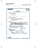
The EC declaration of conformity for all applicable European directives for this product can 
be found on the Rosemount website at www.rosemount.com. A hard copy may be obtained 
by contacting your local sales representative.

(continued on page 16)

00825-0100-4420_Rev_DA.fm  Page 15  Friday, July 17, 2009  10:15 AM

Summary of Contents for Smart Wireless Gateway 1420

Page 1: ... July 2009 1420 Wireless Gateway Step 1 Initial Connection for Configuration Step 2 Basic Security and Time Configuration Step 3 Basic Ethernet or Serial Configuration Step 4 Mount and Connect the Gateway EC Declaration of Conformity Start End 1420 Wireless Gateway ...

Page 2: ...ices Please review the Hazardous Locations Certifications for any restrictions associated with a safe installation Electrical shock can result in death or serious injury Avoid contact with the leads and terminals High voltage that may be present on leads can cause electrical shock WARNING Explosion Hazard Do not disconnect equipment when a flammable or combustible atmosphere is present IMPORTANT N...

Page 3: ...network is used carefully record the current IP address and other settings so the PC laptop can be returned to its original network when configuration of the 1420 is finished Perform the following steps to establish a local connection with the 1420 Wireless Gateway 1 On the PC laptop install the Java Plug in found on the CD provided with the 1420 The Plug in can also be found at http java com 2 Un...

Page 4: ...ings windows that have opened 3 Using the supplied crossover Ethernet cable attach your PC laptop to the 1420 s P1 Ethernet Receptacle far right Ethernet receptacle WARNING Do not connect to the Power Over Ethernet POE port This port supplies power and could potentially damage the PC laptop A B S S S S S 24V DC 24V DC Power Input Power Input Modbus Modbus Not Used Not Used Not Used Not Used Not Us...

Page 5: ...0 Wireless Gateway 5 4 Open a standard web browser Internet Explorer Mozilla Firefox or similar 5 Uncheck proxies Tools Internet Options Connections LAN Settings 6 Access the 1420 s default web page at https 192 168 1 10 a Log on as User admin b Password default ...

Page 6: ...Quick Installation Guide 00825 0100 4420 Rev DA July 2009 1420 Wireless Gateway 6 c Click Yes to proceed through the Security Alert The 1420 Home Page will appear as shown below ...

Page 7: ...ECURITY AND TIME CONFIGURATION To configure the basic security of the 1420 Wireless Gateway perform the following steps 1 Navigate to Setup Security User Accounts 2 Set and confirm new passwords for each of the access levels 3 Click Submit 4 Navigate to Setup Time 5 Select method and click Submit ...

Page 8: ...a wired connection use Port 1 P1 IT Process Control Network Administrator or Technician can provide the following a 1420 fixed IP Address or DHCP Host Name b Netmask Subnet Mask c Gateway BEST PRACTICE Keep these values in a secure location not accessible by unauthorized personnel 2 Configure 1420 Ethernet IP settings a Access the 1420 with Administrator access b Navigate to Setup Internet Protoco...

Page 9: ...e 1420 Web Interface with Administrator access b Navigate to Setup Modbus Communication c Click Enable Modbus d Configure the 1420 Modbus Communication settings to match the Host Modbus settings NOTE Modbus communications will fail if they are not configured identically on the Host and the 1420 e Click Submit and proceed with restart 2 When configuration is completed disconnect the PC laptop from ...

Page 10: ...he gateway by doing the following 1 Insert one U bolt around the pipe and through the top mounting holes of the pipe mount and the 1420 and another U bolt through the bottom mounting holes of the pipe mount and the 1420 2 Using a 1 2 inch socket head wrench fasten the nuts to the U bolts and tighten BEST PRACTICE When mounting outside best practice is to run the Serial or primary Ethernet cable P1...

Page 11: ... work area supervisor The Smart Wireless Gateway remote antenna options are specifically engineered to provide installation flexibility while optimizing wireless performance and maintaining local spectrum approvals Each remote antenna kit contains 50 ft 15 2 m of LMR 400 coaxial cable and a high gain antenna To maintain wireless performance and avoid non compliance with local spectrum regulations ...

Page 12: ...f the WL2 Option 1 Mount the antenna on a 2 in 0 05 m pipe mast using the supplied equipment 2 Attach the lightning arrestor to the top of the Gateway 3 Use the LMR 400 coaxial cable to connect the antenna to the lightning arrestor 4 Seal each connection between the Gateway lightning arrestor cable and antenna with the weather proof tape Antenna 50 ft 15 2 m cable Lightning Arrestor WL2 WL2 Antenn...

Page 13: ...g arrestor and antenna 4 Seal each connection between the Gateway lightning arrestor cables and antenna with the weather proof tape Any spare lengths of coaxial cable should be placed in 12 in 0 3 m coils Ensure that the mounting mast and lightning arrestor are grounded in accordance with local national electrical codes Example of Mounting a Remote Antenna Ground to Lightning Arrestor Control Equi...

Page 14: ...e systems this is reversed For 4 wire systems see Figure 2 Figure 2 Typical Full Duplex 4 wire to Half Duplex 2 wire Conversion Diagram Confirm wiring configuration with host system documentation Supply Power After mounting is complete supply power to the 1420 according to the following steps 1 Ground the 1420 using suitable grounding methods There is a case ground lug located near the terminal bl...

Page 15: ...n for FM As standard the Gateway has been examined and tested to determine that the design meets basic electrical mechanical and fire protection requirements by FM a nationally recognized testing laboratory NRTL as accredited by the Federal Occupational Safety and Health Administration OSHA North American Certifications N5 FM Division 2 Non Incendive Certificate Number 3028321 Nonincendive for Cla...

Page 16: ... The Apparatus is not capable of withstanding the 500V insulation test required by Clause 9 4 of EN 60079 15 2005 This must be taken into account when installing the apparatus ND ATEX Dust Certificate Number Baseefa 07ATEX0057 EX tD A 22 IP66 T135 40 C Ta 60 C Ex nA nL IIC T4 T4 40 C Ta 60 C II 3D Vmax 28V N7 IECEx Type n Certificate Number IECEx BAS 07 0012X Ex nC IIC T4 40 C Ta 60 C Rated Voltag...

Page 17: ...ateway ZZZ ZZZ ZZZ ZZZ Locations Serial Card Location Serial Card ID Serial Card Termination A Tx Serial Card Termination B Rx Setting Value Options on 1420 Default in Bold Modbus Slave Address 1 247 Baud Rate 9600 19200 38400 57600 Parity None Even Odd Stop Bits 1 2 Response Delay Time 0 ms Configurable in ms Unmapped Register Read Response Zero Illegal Data Unmapped Register Write Response OK Il...

Page 18: ...Quick Installation Guide 00825 0100 4420 Rev DA July 2009 1420 Wireless Gateway 18 Figure 3 EC Declaration of Conformity for 1420 Wireless Gateway ...

Page 19: ...Quick Installation Guide 00825 0100 4420 Rev DA July 2009 1420 Wireless Gateway 19 ...

Page 20: ...Quick Installation Guide 00825 0100 4420 Rev DA July 2009 1420 Wireless Gateway 20 ...

Reviews: