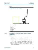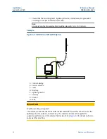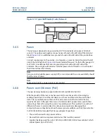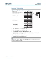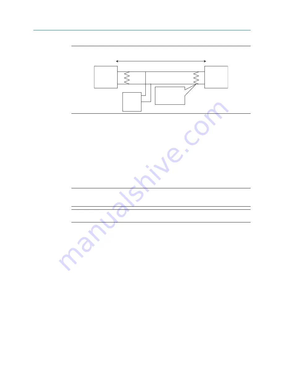
Figure 3-10: Typical Half Duplex (2-wire) Network
Up to 4000 ft. (1220 m)
Device 1
A
B
Terminators required
only for high data
rates and long cable
runs
Device N
(up to 32
possible)
Device 2
3.4.5
Power
The Gateway is designed to be powered by 24 VDC (nominal) and requires 250 mA of
current. The positive and negative connections are found on the left side of the terminal
block (
). An additional case ground is found on the left side of the junction box
enclosure.
Connect supply power to the po and negative – power terminals found on the left
side of the terminal block (
). Recommended torque is 7 in-lb and the gauge is 12
to 22 AWG. An additional internal case ground can be found on the left side of the
enclosure. The wiring should include an external power shut-off switch or circuit breaker
that is located near the Gateway.
Note
Using an uninterruptible power supply (UPS) is recommended to ensure availability should
there be a loss of power.
Note
When using PoE PD, a power supply is not required.
3.4.6
Power over Ethernet (PoE)
The new Gateway hardware supports IEEE 802.3af and IEEE 802.3at PoE.
With the growth of Ethernet, many have wanted to save time and cost on wiring by
sending power down to an Ethernet device over the same Ethernet cable used to haul
data. This is possible because there are four extra wires in an Ethernet cable that are
typically not used. In the past there was no formal standard, people came up with their
own wiring schemes for using these wires to provide power. This resulted in a number of
different schemes to exist and lead to confusion as people were damaging their
computers because they did not know there was power available over the Ethernet cable.
In 2003, IEEE 802.3af standard for PoE was adopted. It specified:
•
The wires that would carry power and how
•
Devices that could source power and devices that could be powered
•
Supplied wattage would be up to 15 Watts (in 2009, IEEE 802.3at was adopted, which
allowed power up to 25 Watts)
Reference Manual
Installation
00809-0200-4420
September 2020
Emerson.com/Rosemount
27
Summary of Contents for Smart Wireless Gateway 1420
Page 1: ...Reference Manual 00809 0200 4420 Rev HE September 2020 Emerson Wireless 1420 Gateway ...
Page 34: ...Installation Reference Manual September 2020 00809 0200 4420 34 Emerson com Rosemount ...
Page 42: ...Commissioning Reference Manual September 2020 00809 0200 4420 42 Emerson com Rosemount ...
Page 62: ...Troubleshooting Reference Manual September 2020 00809 0200 4420 62 Emerson com Rosemount ...
Page 84: ...DeltaV Ready Reference Manual September 2020 00809 0200 4420 84 Emerson com Rosemount ...
Page 95: ...Reference Manual 00809 0200 4420 September 2020 Emerson com Rosemount 95 ...


