Safety
Information
Introduction
Product
information
System
design
Mechanical
installation
Electrical
installation
Getting
started
Optimisation
Parameters
Technical
data
Component
sizing
Diagnostics
Unidrive SP Regen Installation Guide
109
Issue Number: 2 www.controltechniques.com
The value of this parameter is used for the thermal protection in regen mode.
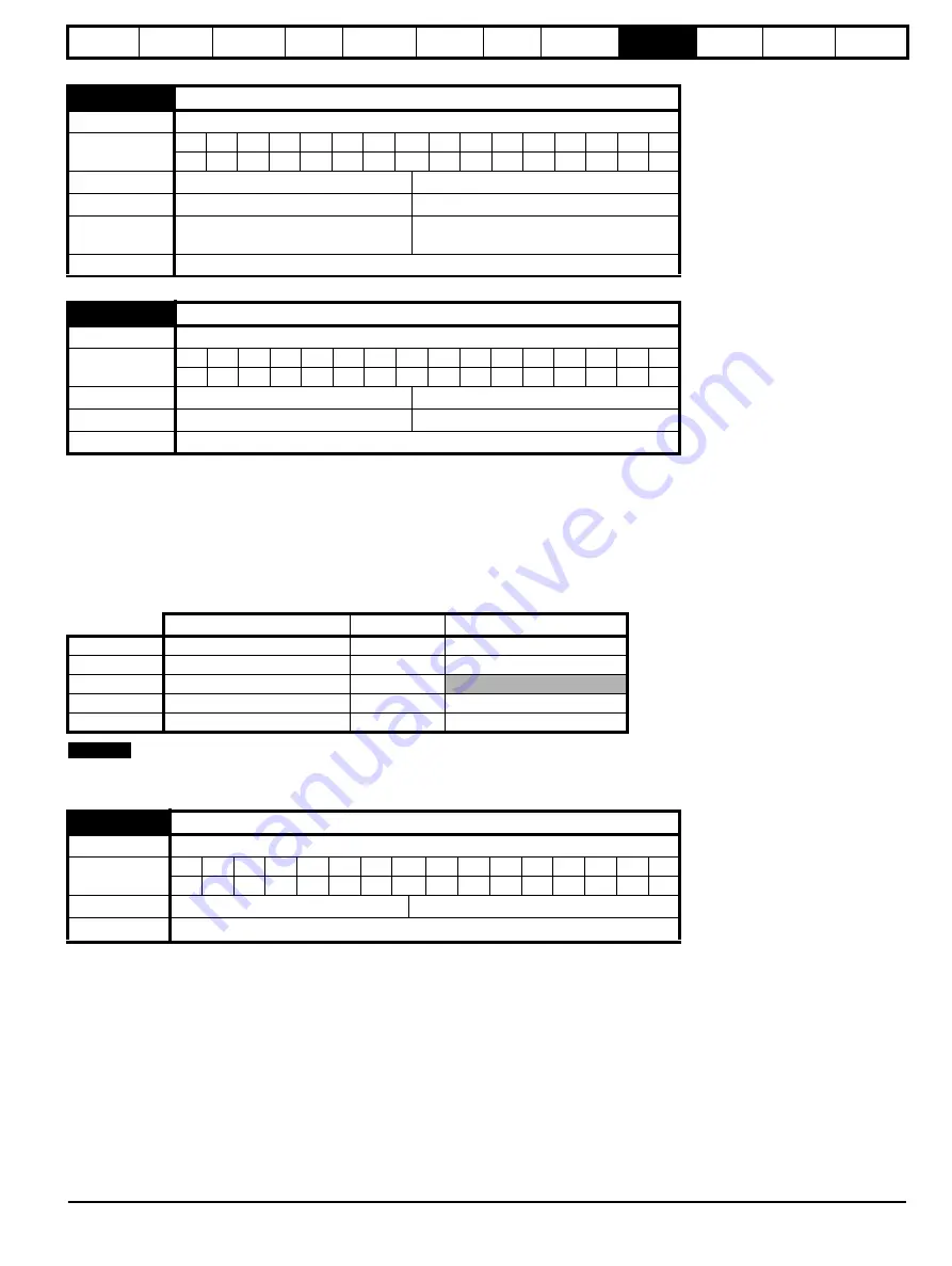
This parameter defines the required switching frequency. The drive may automatically reduce the actual switching frequency (without changing this
parameter) if the power stage becomes too hot. The switching frequency can reduce from 12kHz to 6kHz to 3kHz, or 16kHz to 8kHz to 4kHz. An
estimate of the IGBT junction temperature is made based on the heatsink temperature and an instantaneous temperature drop using the drive output
current and switching frequency. The estimated IGBT junction temperature is displayed in Pr
7.34
. If the temperature exceeds 135°C the switching
frequency is reduced if this is possible (i.e >4kHz) and this mode is enabled (see Pr
on page 109). Reducing the switching frequency reduces the
drive losses and the junction temperature displayed in Pr
7.34
also reduces. If the load condition persists the junction temperature may continue to
rise. If the temperature exceeds 145°C and the switching frequency cannot be reduced the drive will initiate an O.ht1 trip. Every 20ms the drive will
attempt to restore the switching frequency if the higher switching frequency will not take the IGBT temperature above 135°C. The following table gives
the sampling rate for different sections of the control system for different switching frequencies.
All switching frequencies can be used in regen mode with reduced losses at the higher switching frequencies.
The drive thermal protection scheme (see Pr
on page 109) reduces the switching frequency automatically when necessary to prevent the drive
from overheating. It is possible to disable this feature by setting this bit parameter to one. If the feature is disabled the drive trips immediately when
the IGBT temperature is too high.
5.07
Regen drive rated current
Drive mode
Regen
Coding
Bit
SP
FI
DE Txt VM DP
ND
RA NC NV
PT
US RW BU PS
1
2
1
1
1
1
Range
Regen
0 to RATED_CURRENT_MAX A
Default
Regen
Drive rated current (Pr
11.32
)
Second motor
parameter
Regen Pr
21.07
Update rate
Background
5.18
Maximum switching frequency
Drive mode
Regen
Coding
Bit
SP
FI
DE Txt VM DP ND RA NC NV
PT
US RW BU PS
1
1
1
1
1
Range
Regen
0 to 5 (3, 4, 6, 8, 12, 16 kHz)
Default
Regen
0 (3 kHz)
Update rate
Background
3, 6, 12kHz
4, 8, 16kHz
Regen
Level 1
3 = 167
µ
s, 6 = 83
µ
s, 12 = 83
µ
s
125
µ
s
Current controllers
Level 2
250
µ
s
250
µ
s
Voltage controller
Level 3
1ms
1ms
Level 4
4ms
4ms
Time critical user interface
Background
N/A
N/A
Non-time critical user interface
5.35
Disable auto-switching frequency change
Drive mode
Regen
Coding
Bit
SP
FI
DE Txt VM DP
ND
RA NC NV
PT
US RW BU
PS
1
1
1
Default
Regen
0
Update rate
Background
NOTE
Summary of Contents for SP1201
Page 219: ......
Page 220: ...0471 0029 02 ...


