Safety
Information
Introduction
Product
information
System
design
Mechanical
installation
Electrical
installation
Getting
started
Optimisation
Parameters
Technical
data
Component
sizing
Diagnostics
Unidrive SP Regen Installation Guide
111
Issue Number: 2 www.controltechniques.com
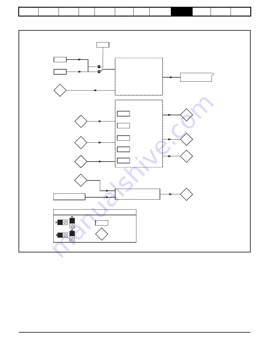
9.6 Menu 6: Clock
Figure 9-5 Menu 6 logic diagram
6.15
6.42
6.17
Power consumption
meter
reset
6.18
Time interval between
filter changes
6.19
Filter change
required/done
6.28
Select clock for trip
log time stamp
6.16
Electricity cost
per kWh
Clock control
6.24
6.25
Power meter
6.26
Running cost
6.27
Time before filter
change due
Inverter enable
6.20
6.21
Power-up
time
6.22
6.23
Run-time
5.03
Total motor
power
0.XX
0.XX
Key
Read-write (RW)
parameter
Read-only (RO)
parameter
Input
terminals
Output
terminals
X
X
X
X
The parameters are all shown at their default settings
6.43
Drive
enable
Control word
Control word
enable
Sequencer
5.05
DC link voltage
Low voltage supply
Drive power supply monitor
6.44
Active supply
6.29
Hardware
enable
Summary of Contents for SP1201
Page 219: ......
Page 220: ...0471 0029 02 ...


