Safety
Information
Introduction
Product
information
System
design
Mechanical
installation
Electrical
installation
Getting
started
Optimisation
Parameters
Technical
data
Component
sizing
Diagnostics
Unidrive SP Regen Installation Guide
9
Issue Number: 2 www.controltechniques.com
2.8 Regen drive system types
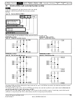
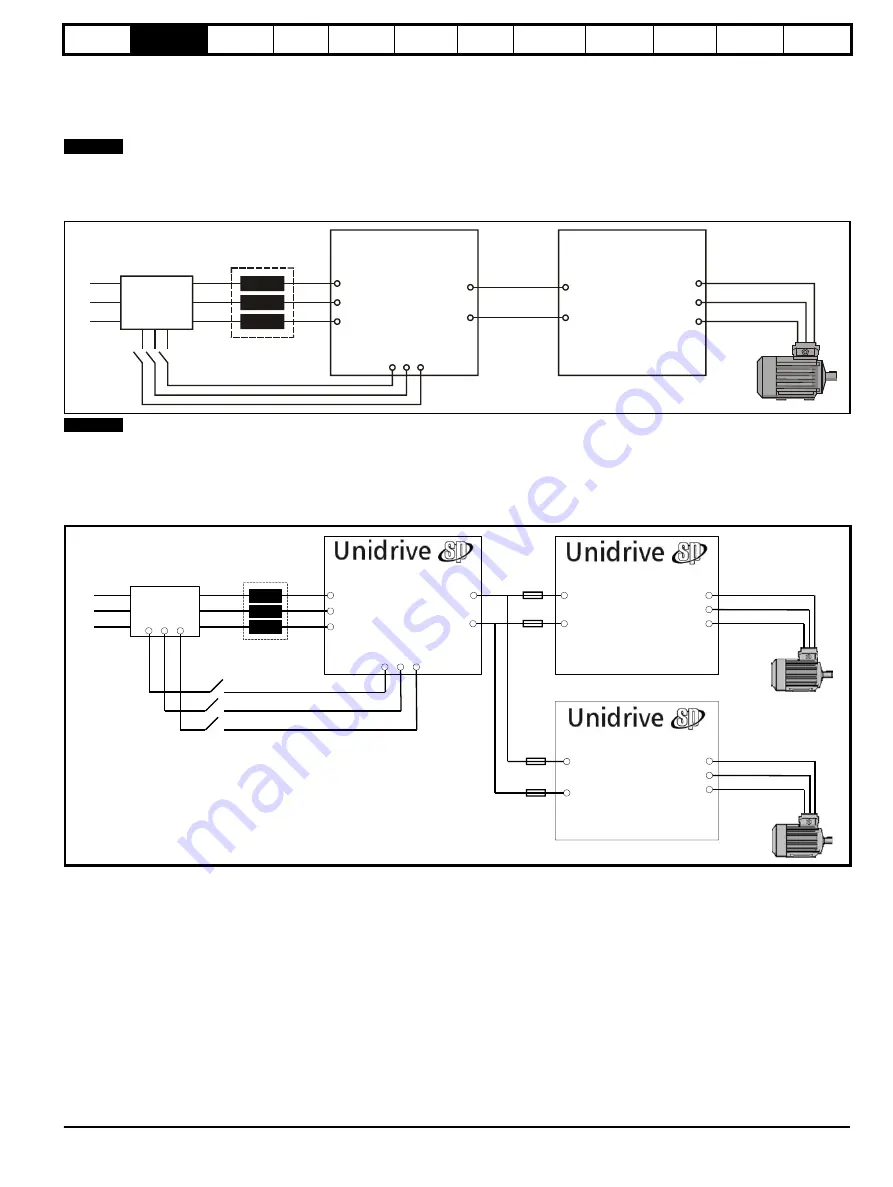
2.8.1 Single Regen, single motoring system
Figure 2-2 shows a typical layout for a standard regen system consisting of a single Regen drive and single motoring drive. In this configuration the
Regen drive is supplying the motoring drive and passing the regenerative energy back to the mains supply.
The power up connections to L1, L2, L3 of the Regen drive are only made during power-up. Once both drives are powered up, this is switched out
and the main regen supply switched in. The auxiliary on the charging circuit to the Regen drive’s L1, L2, L3 connections for power up must be closed
(charging supply removed) before the Regen drive can be enabled.
Figure 2-2 Single Regen, single motoring system
For the above single Regen, single motoring configuration; the Regen drive must be of the same frame size or larger.
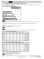
2.8.2 Single Regen, multiple motoring system
Figure 2-4 shows the layout for a regen system consisting of a single Regen drive with multiple motoring drives. In this configuration the Regen drive
is sized to the total power of all motoring drives.
Figure 2-3 Single Regen, multiple motoring system
It is also possible to have a single Regen drive powering multiple motoring drives as shown with the power up connections also being provided via the
Regen drives L1, L2, L3 inputs and using the Regen drives own internal softstart.
In this arrangement the total capacitance of the motoring drives must not exceed the capacitance of the Regen drive, in cases where this does please
contact Technical Support.
NOTE
Regen drive
L1
L2
L3
Additional
circuitry
Regen
inductor
U
V
W
AC supply
connection
U
+DC
-DC
DC bus
connections
Motoring drive
+DC
-DC
U
U
W
V
L1 L2 L3
Power up only
Common
Motor
Connection
NOTE
U
V
W
AC Supply
Connection
Regen Drive
DC Bus
Connections
L1
L2
L3
Regen
Inductor
Additional
Circuitry
-DC
+DC
U
V
W
-DC
+DC
Motor
Connection
Motoring Drive
U
V
W
Motor
Connection
Motoring Drive
-DC
+DC
L1 L2 L3
Power up only
Summary of Contents for SP1201
Page 219: ......
Page 220: ...0471 0029 02 ...


