background image

Safety 

Information

Introduction

Product 

information

System 

design

Mechanical 

installation

Electrical 

installation

Getting 

started

Optimisation

Parameters

Technical 

data

Component 

sizing

Diagnostics

42

 Unidrive SP Regen Installation Guide

www.controltechniques.com                                                       Issue Number: 2

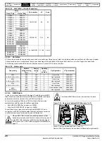
Table 4-7 575V Regen system maximum cable length

Table 4-8 690V Regen system maximum cable length

If the cable length in the above table is exceeded, additional components 
are required. Refer to section 4.6

Exceeding maximum cable length

.

4.5      Cable types and lengths

Since capacitance in the cabling causes loading, ensure the cable length 
does not exceed the values given.
Use 105

°

C (221

°

F) (UL 60/75

°

C temp rise) PVC-insulated cable with 

copper conductors having a suitable voltage rating, for the following 
power connections:

AC supply to external EMC filter (when used)

AC supply (or external EMC filter) to Regen drive

Regen drive to motoring drive (or busbar arrangement could be 
used)

Motoring drive to motor

4.6      Exceeding maximum cable length

If the total maximum length specified is exceeded, the increased 
circulating currents caused by the extra cable capacitance will have an 
effect on the other parts of the system. This will necessitate additional 
components to be added to the standard arrangement.

4.6.1     Regen inductor

If the maximum cable length specified is exceeded this will introduce 
increased heating of the regen inductor. To overcome the additional 
heating forced cooling should be introduced into the system as specified 
in the following table.
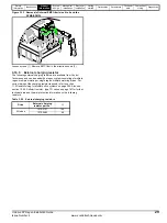
The forced cooling should be positioned as shown below to provide the 
specified airflow directly onto the regen inductor windings.

Figure 4-6 Location of forced cooling

Table 4-9 200V Regen system exceeding maximum cable lengths

Model

575V Nominal AC supply voltage

Maximum permissible cable length 

3kHz

4kHz

6kHz

8kHz

12kHz

16kHz

SP3501

200m 

(660ft)

150m 

(490ft)

100m 

(330ft)

75m 

(245ft)

SP3502
SP3503
SP3504
SP3505
SP3506
SP3507

Model

690V Nominal AC supply voltage

Maximum permissible cable length 

3kHz

4kHz

6kHz

8kHz

12kHz

16kHz

SP4601

200m 

(660ft)

185m 

(607ft)

125m 

(410ft)

90m 

(295ft)

SP4602
SP4603
SP4604
SP4605
SP4606
SP5601
SP5602
SP6601
SP6602

SPMA1601
SPMA1602
SPMD1601
SPMD1602
SPMD1603
SPMD1604

Model

200V Nominal AC supply voltage

Maximum permissible cable length with forced cooling

3kHz 4kHz 6kHz 8kHz 12kHz 16kHz

Forced 

cooling 

required

SP1201

65m (210ft)

50m 

(165ft)

37m 

(120ft)

Air flow >

160m

3

 / hr

SP1202

100m (330ft)

75m 

(245ft)

SP1203

130m (425ft)

100m 

(330ft)

SP1204

200m 

(660ft)

150m 

(490ft)

SP2201
SP2202
SP2203
SP3201
SP3202
SP4201

65m 

(210ft)

65m 

(210ft)

65m 

(210ft)

65m 

(210ft)

SP4202
SP4203
SP5201

250m 

(820ft)

185m 

(607ft)

125m 

(410ft)

90m 

(295ft)

SP5202

SPMD1201

250m 

(820ft)

185m 

(607ft)

125m 

(410ft)

SPMD1202
SPMD1203
SPMD1204

Summary of Contents for SP1201

Page 1: ...Installation Guide U Regen 200V 400V 575V 690V Part Number 0471 0029 02 Issue 2 www controltechniques com ...

Page 2: ...ising the environmental impacts of its manufacturing operations and of its products throughout their life cycle To this end we operate an Environmental Management System EMS which is certified to the International Standard ISO 14001 Further information on the EMS our Environmental Policy and other relevant information is available on request or can be found at www greendrives com The electronic va...

Page 3: ...ed when working with or designing a system using the drive This guide should be read in line with the relevant User Guide also which contains additional information which may be required whilst designing and commissioning a regen system This map of the user guide helps to find the right sections for the task you wish to complete NOTE Familiarisation System design System design Programming and comm...

Page 4: ...ure 64 6 Electrical Installation 65 6 1 Power connections 66 6 2 AC supplies 74 6 3 Cable and fuse ratings 75 6 4 EMC Electromagnetic compatibility 77 6 5 External EMC filter 78 6 6 Control connections 83 7 Getting started 86 7 1 Regen parameter settings 86 7 2 Regen drive sequencing 86 7 3 Regen drive commissioning 87 7 4 Motoring drive commissioning 88 8 Optimisation 89 8 1 Power feed forward co...

Page 5: ...e SP Regen Installation Guide 5 Issue Number 2 www controltechniques com 12 Diagnostics 206 12 1 Trip indications 206 12 2 Alarm indications 215 12 3 Status indications 215 12 4 Displaying the trip history 215 ...

Page 6: ... application where a malfunction of the drive or its control system could lead to or allow damage loss or injury a risk analysis must be carried out and where necessary further measures taken to reduce the risk for example an over speed protection device in case of failure of the speed control or a fail safe mechanical brake in case of loss of motor braking 1 4 Environmental limits Instructions in...

Page 7: ...or can be higher than the available AC mains supply The Regen drive will synchronise to any frequency between 30 and 100Hz provided the supply voltage is within the supply requirements operating frequency range of 48Hz to 65Hz Under conditions of AC mains instability a Unidrive SP Regen system can continue to operate down to approximately 75Vac 200V product 150Vac 400V product 225Vac 575V and 690V...

Page 8: ...culated Once the synchronization is complete the phase locked loop PLL is set up At this point the whole control system could be started and should operate without any large transients To improve the robustness of the start up phase a further short test pulse voltage vector with the same magnitude and phase as the estimated supply voltage vector is applied This is to detect measurement errors that...

Page 9: ...single Regen single motoring configuration the Regen drive must be of the same frame size or larger 2 8 2 Single Regen multiple motoring system Figure 2 4 shows the layout for a regen system consisting of a single Regen drive with multiple motoring drives In this configuration the Regen drive is sized to the total power of all motoring drives Figure 2 3 Single Regen multiple motoring system It is ...

Page 10: ...ated by the additional capacitance of the multiple motoring drives The charging circuit can consist of either a Unidrive SPMC rectifier module or an external charging resistor as detailed in Chapter 4 System design Regen drive L1 L2 L3 Additional circuitry Regen inductor U V W AC supply connection U DC DC Motoring drive 2 DC DC U U W V Motoring drive 3 DC DC U U W V Motoring drive 1 DC DC U U W V ...

Page 11: ... design on page 30 Special care should be taken when designing a multiple regen and multiple motoring drive system ensuring that all the required fusing is in place on both the common DC Bus connections and the AC supply to all regen drives Figure 2 5 Multiple Regen multiple motoring system All drives paralleled must be of the same frame size and a derating also applies as specified in Chapter 3 P...

Page 12: ...brake control Current rating step Unidrive SP product line SPMA SPMD Power module power stages for custom drive systems DC input Power module power stages for custom drive systems AC input Wall mount SPX 1 4 0 1 SP Solutions platform complete inverter drive SP1201 I P 200 240V 50 60Hz 3ph 6 6A O P 0 240V 4 3 5 2A Model Input voltage rating Input frequency No of phases Typical input current for Nor...

Page 13: ...s Table 3 1 200V Drive ratings 200V to 240V 10 Model Normal Duty Heavy Duty Maximum continuous output current Nominal power at 220V Motor power at 230V Maximum continuous output current Nominal power at 220V Motor power at 230V A kW hp A kW hp 1201 5 2 1 1 1 5 4 3 0 75 1 0 1202 6 8 1 5 2 0 5 8 1 1 1 5 1203 9 6 2 2 3 0 7 5 1 5 2 0 1204 11 3 0 3 0 10 6 2 2 3 0 2201 15 5 4 0 5 0 12 6 3 0 3 0 2202 22 ...

Page 14: ...formation refer to both the Unidrive SP and SPM User Guides Model Normal Duty Heavy Duty Maximum continuous input current Typical motor power at 400V Typical motor power at 460V Maximum continuous input current Typical motor power at 400V Typical motor power at 460V A kW hp A kW hp 1405 8 8 4 0 5 0 7 6 3 0 5 0 1406 11 5 5 7 5 9 5 4 0 5 0 2401 15 3 7 5 10 13 5 5 10 2402 21 11 15 16 5 7 5 10 2403 29...

Page 15: ...rmation refer to both the Unidrive SP and SPM User Guides Model Normal Duty Heavy Duty Maximum continuous output current Nominal power at 575V Motor power at 575V Maximum continuous output current Nominal power at 575V Motor power at 575V A kW hp A kW hp 3501 5 4 3 0 3 0 4 1 2 2 2 0 3502 6 1 4 0 5 0 5 4 3 0 3 0 3503 8 4 5 5 7 5 6 1 4 0 5 0 3504 11 7 5 10 9 5 5 5 7 5 3505 16 11 15 12 7 5 10 3506 22...

Page 16: ...er information refer to both the Unidrive SP and SPM User Guides Model Normal Duty Heavy Duty Maximum continuous output current Nominal power at 690V Motor power at 690V Maximum continuous output current Nominal power at 690V Motor power at 690V A kW hp A kW hp 4601 22 18 5 25 19 15 20 4602 27 22 30 22 18 5 25 4603 36 30 40 27 22 30 4604 43 37 50 36 30 40 4605 52 45 60 43 37 50 4606 62 55 75 52 45...

Page 17: ...Solutions Module slot 3 Rating label Status LED Approvals label Relay terminals DC Bus output High current EMC capacitor must be removed 3 4 AC supply U V W EMC capacitor must be removed 5 EMC capacitor must be removed DC Bus output High current AC supply U V W 6 EMC capacitor must be removed DC Bus output High current AC supply U V W DC Bus output High current EMC capacitor must be removed AC sup...

Page 18: ...odule slot 2 SMARTCARD slot Keypad connection Serial port connector Encoder connection Control terminals Solutions Module slot 1 Solutions Module slot 3 Rating label Status LED Approvals label B Relay terminals EMC capacitor must be removed Heatsink fan supply connections Master interface Slave interface SPMA SPMD Output connections to slave Input from Master Output to slave Status LED Cover Base ...

Page 19: ... 2601 Figure 3 8 Dual diode rectifier The Unidrive SPMC is a half controlled thyristor bridge is used as a front end to the SPMD inverter module or as a stand alone rectifier for several smaller drives Soft start is built in The Unidrive SPMU is used as a front end to the SPMD inverter module or as a stand alone rectifier for several smaller drives Softstart must be supplied externally using a res...

Page 20: ... frame size SPMU Uncontrolled 6 690V Model Typical input current A Maximum input current A Typical DC current Adc Semi conductor fuse in series with HRC fuse Cable sizes AC input DC output HRC IEC class gG UL class J Semi conductor IEC class aR mm2 AWG mm2 AWG SPMC1402 339 344 379 540 400 2 x 120 2 x 4 0 2 x 120 2 x 4 0 SPMC2402 2 x 308 2 x 312 2 x 345 450 400 2 x 120 2 x 4 0 2 x 120 2 x 4 0 SPMU1...

Page 21: ...en lost OFF ON Phase loss OFF ON Any of the following Internal fault Check that rectifier is an SPMU This could indicate that unit is an SPMC ON OFF Any of the following Snubber overheating due to excessive cable charging current or supply notching Rectifier heatsink over temperature Rectifier PCB over temperature Status input wire break ON OFF Any of the following Rectifier heatsink over temperat...

Page 22: ...Current rating step OTL Output sharing choke OTL 4 0 1 0 Single 1 Dual Voltage rating 4 380V to 480V 6 500V to 690V NOTE When connecting either SPMA or SPMD drives in parallel they must be de rated by 5 CAUTION NOTE Model Current A Inductance µH Width W mm Depth D mm Height H mm Weight kg Part No OTL401 221 40 1 240 220 210 20 4401 0197 00 OTL402 267 34 242 220 205 20 4401 0198 00 OTL403 313 28 5 ...

Page 23: ...Options Figure 3 11 Options available for Unidrive SP Regen A SMARTCARD is provided with the Unidrive SP as standard Only one SMARTCARD can be fitted at any one time Position feedback modules will still function with a drive configured in regen mode however this would only be required where the Regen drive is to be used to provide additional Solutions Module slots for the motoring drive Keypad Aut...

Page 24: ...upport White SM Applications Lite Applications Processor 2nd processor for running pre defined and or customer created application software Fieldbus Purple SM PROFIBUS DP Profibus option PROFIBUS DP adapter for communications with the Unidrive SP Medium Grey SM DeviceNet DeviceNet option Devicenet adapter for communications with the Unidrive SP Dark Grey SM INTERBUS Interbus option Interbus adapte...

Page 25: ...0 SPMD1201 SP5202 4401 0321 0 22 156 0 SPMD1202 SPMD1201 4401 0322 0 18 192 0 SPMD1203 SPMD1202 4401 0323 0 14 250 0 SPMD1204 SPMD1203 4401 0324 0 11 312 0 SPMD1204 4401 0325 0 10 350 0 CAUTION Drive Part number mH Arms Heavy Duty Normal Duty SP1405 SP1405 4401 0001 6 30 9 5 SP1406 4401 0001 6 30 9 5 SP1406 4401 0002 5 00 12 0 SP2401 SP2401 4401 0003 3 75 16 0 SP2402 4401 0003 3 75 16 0 SP2403 SP2...

Page 26: ... 0 SP5201 SP4203 4401 1319 0 16 105 0 SP5202 SP5201 4401 1320 0 13 130 0 SPMD1201 SP5202 4401 1321 0 11 156 0 SPMD1202 SPMD1201 4401 1322 0 088 192 0 SPMD1203 SPMD1202 4401 1323 0 068 250 0 SPMD1204 SPMD1203 4401 1324 0 055 312 0 SPMD1204 4401 1325 0 048 350 0 Drive Part number mH Arms Heavy Duty Normal Duty SP1405 SP1405 4401 0162 3 16 9 5 SP1406 4401 0162 3 16 9 5 SP1406 4401 0163 2 50 12 0 SP24...

Page 27: ... 0 SP6602 SP6601 4401 1219 0 40 125 0 SPMA1601 4401 1218 0 50 100 0 SPMD1601 4401 1218 0 50 100 0 SPMA1602 SPMA1601 4401 1219 0 40 125 0 SPMD1602 SPMD1601 4401 1219 0 40 125 0 SPMA1602 4401 1220 0 35 144 0 SPMD1602 4401 1220 0 35 144 0 SPMD1603 SP6602 4401 1220 0 35 144 0 SPMD1604 SPMD1603 4401 1221 0 30 168 0 SPMD1604 4401 1222 0 26 192 0 Drive Part number uF Arms Heavy Duty Normal Duty SP1203 SP...

Page 28: ...n with EMC installation guidelines they will reduce emissions to sufficiently low levels to minimise the risk of disturbance Figure 3 12 Removal of internal EMC filter size 1 to 3 Loosen remove screws as shown 1 and 2 Remove filter 3 and ensure the screws are replaced and re tightened 4 Drive Part number uF Arms Heavy Duty Normal Duty SP4601 SP4601 1668 7833 8 3 4 3 SP4602 SP4602 SP4603 SP4603 SP4...

Page 29: ...arging resistor The following external charging resistors are available from Control Techniques and can be used with a regen system consisting of multiple regen multiple motoring or single regen multiple motoring drives For correct sizing of the charging resistor required refer to section 11 2 Resistor sizing for multiple drive systems on page 204 Also see section 10 4 2 Softstart resistor type TG...

Page 30: ...e is supplying 175 maximum current and the Regen drive has its 380V supply at the lower limits of 10 342Vac then with a regen current limit of 150 The Regen drive maximum available power is 1 73 x 1 5 x 96 x 342 85 1kW The motoring drives maximum power is 1 73 x 1 75 x 96 x 400 x 0 95 110 4kW Drive losses 2 x Unidrive SP 4403 1 952kW The Regen drive is also required to supply the Regen and motorin...

Page 31: ...t information System design Mechanical installation Electrical installation Getting started Optimisation Parameters Technical data Component sizing Diagnostics Unidrive SP Regen Installation Guide 31 Issue Number 2 www controltechniques com ...

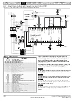
Page 32: ... Connections Motoring drive DC Connections 24 output Enable motor drive Contactor closed 0 common Drive enable K2 Rly 1 optional L1 L2 L3 PE Aux 3 C1 OPD1 Aux 1 Regen drive S1 Aux 1 K2 Aux 2a Aux 2a Regen inductor thermistor 0V common V V Drive healthy Reset input Aux 3 S6 Contactor control VDR5 Vsupply K3 Charging branch circuit Aux 2b K3 Vsupply Aux 2b Note Surge suppressors to be fiited to cont...

Page 33: ...es com VDR4 VDR5 and VDR6 when operating with a 690Vac supply should consist of two varistors each in series as detailed in Table 3 24 on page 28 U V W L1 L2 L3 PE DC DC DC DC 21 1 2 3 4 5 6 7 8 9 10 11 41 42 22 23 24 25 26 27 28 29 30 31 T 30 T 24 S5 Mt 1 AC Supply NOT USED Motor Connections Motoring drive DC Connections U V W PE S2 S3 S4 Drive enable 0 common Run forward Run reverse Motor thermi...

Page 34: ...using a standard line reactor if required U V W L1 L2 L3 PE DC DC DC DC 21 1 2 3 4 5 6 7 8 9 10 11 41 42 22 23 24 25 26 27 28 29 30 31 K2 L2 RFI F1 F2 F3 VDR2 VDR3 VDR4 VDR5 VDR6 Tc 1 L1 L2 L3 AC Supply Connections Motoring drive DC Connections 24 output Enable motor drive Contactor closed 0 common Drive enable C1 OPD1 Aux 1 T 30 T 24 Rly 1 optional L1 Regen drive S1 K1 Aux 2a Unidrive SPMC L1 L2 ...

Page 35: ...ors when the 24Vdc is present Fitting a 5A relay interlocked or a normally closed auxiliary contact to the Regen drives main contactor to switch the 24V supply will allow the SPMC to charge the common DC bus then be disabled optional The total amount of capacitance on the common DC bus that the SPMC can drive is limited due to the inrush current produced during power up and during brownouts See th...

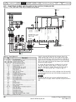
Page 36: ...1 1 2 3 4 5 6 7 8 9 10 11 41 42 22 23 24 25 26 27 28 29 30 31 K2 L2 RFI F1 F2 F3 VDR1 VDR2 VDR3 VDR4 VDR5 VDR6 Tc 1 L1 L2 L3 K2 Aux 2a AC Supply Connections Motoring drive DC Connections Aux 3 OPD2 Rs 1 24 output En ble motor drive Contactor closed 0 common Drive enable K3 T 30 T 24 Rly 1 optional L1 Regen drive S1 Aux 1 K1 Aux 2a Regen inductor thermistor 0V common V V a S6 Aux 3 Drive healthy Re...

Page 37: ...ee Chapter 10 Technical data on page 183 for fuse rating information DC DC F4 F5 U V W L1 L2 L3 PE DC DC 21 1 2 3 4 5 6 7 8 9 10 11 41 42 22 23 24 25 26 27 28 29 30 31 T 30 T 24 S5 Mt 1 AC Supply Connections NOT USED Connections Motoring drive DC Connections U V W PE S2 S3 S4 Drive enable 0V common Drive reset Run forward Run reverse Motor thermistor 0V common Motoring drive F6 F7 U V W L1 L2 L3 P...

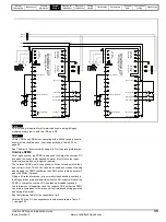
Page 38: ...ntactor closed 0 common Drive enable Rly 1 optional Regen drive 1 master S1 Unidrive SPMC L1 85 84 DC DC F16 F15 24Vdc external supply 0V common Regen inductor thermistor 0V common V Aux 2 V Aux 1 K2 AC Supply Connections not used Aux 3 L2 L3 F11 F10 F12 K3 L2 F14 F13 S6 Drive healthy Reset input U V W L1 L2 L3 PE DC DC 21 1 2 3 4 5 6 7 8 9 10 11 41 42 22 23 24 25 26 27 28 29 30 31 AC Supply Conne...

Page 39: ...AC fuses Aux 2a K2 NO auxiliary contact regen 1 F7 F8 F9 Regen drive 2 AC fuses Aux 2b K2 NC auxiliary contact regen 1 F10 F11 F12 SPMC AC fusing Aux 2c K2 NC auxiliary contact regen 1 F13 F14 DC Bus fusing to SPMC Aux 3 K3 NC auxiliary contact F15 F16 F17 F18 DC Bus fusing to regen drives Aux 4a K4 NO auxiliary contact regen 2 F19 F20 F21 F22 DC Bus fusing to motoring drive Aux 4b K4 NC auxiliary...

Page 40: ... ISC Short circuit current of supply at point of coupling with other equipment ISupply Rated current of supply The switching frequency filter may be omitted if the following relation is true If the short circuit current is not known then a reasonable estimate can be made if it is assumed that the fault current of the supply is 20 times the rated current This is very commonly the case where the sup...

Page 41: ...e Motoring drive Regen inductor Motor Cable length B Cable length A Cable length C Model 200V Nominal AC supply voltage Maximum permissible cable length 3kHz 4kHz 6kHz 8kHz 12kHz 16kHz SP1201 65m 210ft 50m 165ft 37m 120ft SP1202 100m 330ft 75m 245ft SP1203 130m 425ft 100m 330ft SP1204 200m 660ft 150m 490ft SP2201 SP2202 SP2203 SP3201 SP3202 SP4201 65m 210ft 65m 210ft 65m 210ft 65m 210ft SP4202 SP4...

Page 42: ...rrangement 4 6 1 Regen inductor If the maximum cable length specified is exceeded this will introduce increased heating of the regen inductor To overcome the additional heating forced cooling should be introduced into the system as specified in the following table The forced cooling should be positioned as shown below to provide the specified airflow directly onto the regen inductor windings Figur...

Page 43: ...to ground carry common mode current When the maximum cable length without additional ventilation specified is exceeded extra circulating currents can result in heating and saturation of the EMC filter To prevent this some capacitance line to ground should be provided as an additional path for this current as shown in Figure 4 8 See also section 4 4 3 Motor connection on page 41 Model 400V Nominal ...

Page 44: ... for simple rectifier input systems 2 for regen systems VDC is DC bus voltage lfs is the sum of the products of motor cable lengths and switching frequencies of all drives in the system including in the case of regenerative systems the Regen drive with the total DC cable length l is total cable length in m fs is switching frequency in kHz If all drives operate at 3kHz the expression can be simplif...

Page 45: ...is not classified as a fire enclosure A separate fire enclosure must be provided 5 2 6 Electromagnetic compatibility Variable speed drives are powerful electronic circuits which can cause electromagnetic interference if not installed correctly with careful attention to the layout of the wiring Some simple routine precautions can prevent disturbance to typical industrial control equipment If it is ...

Page 46: ...60 x 140 9 4401 0315 42 0 81 200 270 200 240 24 160 x 160 9 4401 0316 56 0 6 264 325 220 320 32 200 x 180 11 4401 0317 68 0 5 299 325 220 320 33 200 x 180 11 4401 0318 80 0 4 298 325 220 320 39 200 x 180 11 4401 0319 105 0 32 338 370 260 360 55 240 x 220 11 4401 0320 130 0 26 394 375 280 360 65 240 x 240 11 4401 0321 156 0 22 475 395 280 360 77 240 x 240 11 4401 0322 192 0 18 526 395 280 360 97 24...

Page 47: ...ng type 4401 0210 19 5 3 268 325 220 320 32 200 x 180 11 A 4401 0211 22 4 6 288 325 220 320 33 200 x 180 11 4401 0212 27 3 8 322 325 220 320 39 200 x 180 11 4401 0213 36 2 8 348 370 260 360 55 240 x 220 11 4401 0214 43 2 4 398 375 280 360 65 240 x 240 11 4401 0215 52 1 9 456 395 280 360 77 240 x 240 11 4401 0216 63 1 6 503 395 280 360 97 240 x 240 11 4401 0217 85 1 20 605 430 300 410 110 280 x 260...

Page 48: ...1311 11 0 1 50 18 150 90 150 4 120 x 47 8 x 18 4401 1312 15 5 1 10 26 150 90 150 4 120 x 47 8 x 18 4401 1313 22 0 70 33 150 90 150 4 120 x 47 8 x 18 4401 1314 31 0 50 37 190 100 180 6 130 x 54 8 x 20 4401 1315 42 0 40 38 190 120 180 10 130 x 74 8 x 20 4401 1316 56 0 30 48 190 160 180 12 130 x 184 8 x 20 4401 1317 68 0 25 58 190 160 180 12 130 x 184 8 x 20 4401 1318 80 0 20 60 190 160 180 13 130 x ...

Page 49: ... 300 180 300 37 204 x 113 10 x 20 4401 0174 180 0 165 170 300 180 300 37 204 x 113 10 x 20 4401 0175 220 0 135 180 300 190 300 49 204 x 123 10 x 20 4401 0176 300 0 100 220 300 200 300 50 204 x 130 10 x 20 4401 1205 350 0 08 300 325 220 325 55 204 x 160 4 x 10 4401 0176 600 0 050 400 410 300 430 110 280 x 260 11 A 4401 0176 900 0 034 530 480 320 500 140 320 x 240 11 4401 0176 1200 0 025 700 480 320...

Page 50: ...ponent sizing Diagnostics 50 Unidrive SP Regen Installation Guide www controltechniques com Issue Number 2 Figure 5 7 Switching frequency filter inductor type 1 dimensions Figure 5 8 Switching frequency filter inductor type 2 dimensions Figure 5 9 Switching frequency filter inductor type 3 dimensions H L D A1 A2 B1 B2 C1 C2 A1 B1 C1 A2 B2 C2 D L H A2 B2 C2 A1 B1 C1 H L D ...

Page 51: ...g chokes 560 REF H L D Model Current A Inductance µH Width W mm Depth D mm Height H mm Cablelength CLa mm Weight kg Part No OTL401 221 40 1 240 220 210 71 5 20 4401 0197 00 OTL402 267 34 242 220 205 20 4401 0198 00 OTL403 313 28 5 242 220 205 25 4401 0199 00 OTL404 378 23 9 242 220 205 25 4401 0200 00 OTL601 135 103 9 242 170 203 20 4401 0201 00 OTL602 156 81 8 242 170 203 20 4401 0202 00 OTL603 1...

Page 52: ... sharing choke Model Current A Inductance µH Width W mm Depth D mm Height H mm Cable length mm Weight kg Part No CLa CLb CLc OTL411 389 5 42 8 300 150 160 335 335 265 8 4401 0188 00 OTL412 470 3 36 7 300 150 160 8 4401 0189 00 OTL413 551 31 1 300 150 160 8 4401 0192 00 OTL414 665 26 6 300 150 160 9 4401 0186 00 OTL611 237 5 110 4 300 150 160 8 4401 0193 00 OTL612 273 6 88 4 300 150 160 8 4401 0194...

Page 53: ...be not any switch fuse or any other disconnecting device in the circuit between the power capacitor and the discharging device Over current and short circuit protection Use HRC fuses or MCCBs for short circuit protection Short circuit protection and connecting cables should be selected so that 1 5 times the rated capacitor current can be permanently handled HRC fuses do not protect a capacitor aga...

Page 54: ...ng Diagnostics 54 Unidrive SP Regen Installation Guide www controltechniques com Issue Number 2 Figure 5 15 3 phase Polecap dimensions Figure 5 16 3 phase Windcap Phasecap dimensions Terminal cover uv resistant Label L 81 2 0 3mm Mxx Torque Nm 16 0 0 1mm 210mm max Cable gland Ø22mm 18mm Marking 16 1mm Mxx Torque T Nm Impregnating Hole Torque T 1 2 Nm SW 17mm L 19 6 0 5mm 16 8 0 5mm ...

Page 55: ...1 3 3 kg 7 3 lb SP3201 to SP3202 4200 6307 3 5 kg 7 7 lb 4200 6306 5 1 kg 11 2 lb SP4201 to SP4203 4200 6406 4 0 kg 8 8 lb 4200 6405 7 8 kg 17 2 lb SP5201 to SP5202 4200 6503 6 8 kg 15 0 lb 4200 6501 12 0 kg 26 5 lb SP1401 to SP1404 4200 6118 1 4 kg 3 1 lb 4200 6121 2 1 kg 4 6 lb SP1405 to SP1406 4200 6119 4200 6120 SP2401 to SP2404 4200 6210 2 0 kg 4 4 lb 4200 6211 3 3 kg 7 3 lb SP3401 to SP3403 ...

Page 56: ...Mount the external EMC filter following the guidelines in section 6 12 5 Compliance with generic emission standards on page 62 Figure 5 21 Size 1 external EMC filter All filter mounting holes are suitable for M6 fasteners Figure 5 17 Footprint mounting the EMC filter Figure 5 18 Bookcase mounting the EMC filter Figure 5 19 Size 4 to 6 mounting of EMC filter Figure 5 20 Mounting the external EMC fi...

Page 57: ...MC filter All filter mounting holes are suitable for M6 fasteners V Ground stud M5 X M6 threaded holes for footprint mounting of the drive Y Footprint mounting holes 6 5mm 0 256in Z Bookcase mounting slots 6 5mm 0 256in wide Y E D Z L2 L1 L3 L 1 L 2 L 3 V X Y Y A B H C W Z Z Cable size 4mm 10AWG 2 CT part no Manufacturer A B C D E H W 4200 6210 Schaffner 371 5 mm 14 626 in 404 5 mm 15 925 in 125 m...

Page 58: ...3 Size 3 external EMC filter Z E D V Ground stud M6 X M6 threaded holes for footprint mounting of the drive Y Footprint mounting holes 6 5mm 0 256in Z Bookcase mounting slots 6 5mm 0 256in wide Cable size 16mm 6AWG 2 V Y Y C W A B H Z Z X X CT part no Manufacturer A B C D E H W 4200 6305 Schaffner 361 mm 14 213 in 396 mm 15 591 in 210 mm 8 268 in 60 mm 2 362 in 30 mm 1 181 in 414 mm 16 299 in 250 ...

Page 59: ...ookcase mounting slots 6 5mm 0 256in wide CT part no Manufacturer A B C D E F H W 4200 6406 Schaffner 260 mm 10 236 in 275 mm 10 827 in 170 mm 6 693 in 100 mm 3 937 in 65 mm 2 559 in 1 5 mm 0 059in 300 mm 11 811 in 225 mm 8 858 in 4200 6408 208 mm 8 189 in 4200 6503 120 mm 4 724 in 85 mm 3 346 in 249 mm 9 803 in 4200 6504 100 mm 3 937 in 65 mm 2 559 in 225 mm 8 858 in 4200 6405 Epcos 150 mm 5 906 ...

Page 60: ... range up to 2500A Schaffner FN3359 300 99 range up to 2400A These filters may not give strict conformity with EN6000 6 4 but in conjunction with EMC installation guidelines they will reduce emissions to sufficiently low levels to minimise the risk of disturbance W V A G I B C D E J J F H Z Z Z Z Z V Z Z Z V Ground stud M10 Z Hole size 10 5mm CT part no Manufacturer A B C D E F G H I J W 4200 6601...

Page 61: ...en components on page 25 5 4 2 Varistors Figure 5 28 Varistor dimensions Table 5 14 Varistor specifications External charging resistor part no Resistance Diameter A mm Length B mm 1270 3157 150Ω 19 1 73 1270 2483 48Ω x 1 22 2 165 1 A B Ø A B C D 24 0mm 33 5mm 21 45mm 0 2 5 0 NOTE Drive rating Varistor voltage rating VRMS Energy rating J Quantity per system Configuration CT part number 200V 200V to...

Page 62: ...nding air by natural convection or external forced air flow the greater the surface area of the enclosure walls the better is the dissipation capability Only the surfaces of the enclosure that are unobstructed not in contact with a wall or floor can dissipate heat Calculate the minimum required unobstructed surface area Ae for the enclosure from Where Ae Unobstructed surface area in m2 1 m2 10 9 f...

Page 63: ...If the enclosure is too large for the space available it can be made smaller only by attending to one or all of the following Using a lower PWM switching frequency to reduce the dissipation in the drives Reducing the ambient temperature outside the enclosure and or applying forced air cooling to the outside of the enclosure Reducing the number of drives in the enclosure Removing other heat generat...

Page 64: ...sary derating to ensure sufficient cooling for the whole of the drive The ambient temperature for the four different combinations is defined below 1 Totally enclosed with no air flow 2 m s over the drive Trate Tint 5 C 2 Totally enclosed with air flow 2 m s over the drive Trate Tint 3 Through panel mounted with no airflow 2 m s over the drive Trate the greater of Text 5 C or Tint 4 Through panel m...

Page 65: ...age after the AC supply has been disconnected If the drive has been energised the AC supply must be isolated at least ten minutes before work may continue Normally the capacitors are discharged by an internal resistor Under certain unusual fault conditions it is possible that the capacitors may fail to discharge or be prevented from being discharged by a voltage applied to the output terminals If ...

Page 66: ...ssue Number 2 6 1 Power connections 6 1 1 AC and DC regen connections Figure 6 1 Unidrive SP size 1 Regen drive power connections L2 L1 L3 U V W AC supply connections BR 48V DC DC DC connections High current DC to motoring drive s Internal EMC filter 1 To be removed PE L1 L2 L3 Refer to Chapter 4 System design L2 L1 L3 U V W BR 48V DC DC Internal EMC filter 1 To be removed PE Regen drive Motoring ...

Page 67: ... used size 1 and 2 only an overload protection device is not required The resistor is designed to fail safely under fault conditions See Figure 6 8 for further information on ground connections 2 L2 L1 L3 U V W PE AC supply connections BR DC1 DC2 48V DC DC Internal EMC filter DC1 DC2 To be removed L1 L2 L3 Refer to Chapter 4 System design 2 L2 L1 L3 U V W PE BR DC1 DC2 DC connections High current ...

Page 68: ...ng resistor supplying the drive from DC low voltage 48V or high voltage or using the drive in a parallel DC bus system The low current DC connection is used only to connect the internal EMC filter See Figure 6 9 for further information on ground connections L2 L1 L3 U V W PE AC supply connections BR DC1 DC2 DC connections High current DC to motoring drive s 48V DC DC Internal EMC filter DC1 DC2 To...

Page 69: ...e Number 2 www controltechniques com Figure 6 4 Unidrive SP size 4 5 and 6 power connections See section 6 1 2 Ground connections U V W AC supply connections L1 L2 L3 DC DC Internal EMC filter 4 Refer to Chapter 4 L1 L2 L3 System design To be removed PE DC Connections High current DC to motoring drive s 5 6 U V W L1 L2 L3 DC DC Internal EMC filter 4 PE 5 6 To be removed Motor Optional ground conne...

Page 70: ...ion Guide www controltechniques com Issue Number 2 Figure 6 5 Unidrive SPMA power connections U V W AC supply connections L1 L2 L3 DC DC Internal EMC filter Refer to Chapter 4 L1 L2 L3 System design To be removed PE DC Connections High current DC to motoring drive s U V W L1 L2 L3 DC DC Internal EMC filter 4 PE 5 6 To be removed Motor Optional ground connection Regen drive Motoring drive Vac suppl...

Page 71: ...idrive SP Regen Installation Guide 71 Issue Number 2 www controltechniques com Figure 6 6 Unidrive SPMD power connections U V W AC supply connections DC DC Internal EMC filter To be removed PE DC Connections High current DC to motoring drive s U V W DC DC Internal EMC filter 4 PE 5 6 To be removed Motor Optional ground connection Regen drive Motoring drive Vac supply SPMA Motor connections SPMD SP...

Page 72: ...controltechniques com Issue Number 2 Figure 6 7 Unidrive SPMC power connections See section 6 1 2 Ground connections U V W AC supply connections DC DC Internal EMC filter To be removed PE DC Connections High current DC to motoring drive s 5 6 U V W DC DC Internal EMC filter PE 5 6 To be removed Motor Optional ground connection Regen drive Motoring drive Vac supply L1 L2 L3 SPMC PE DC DC PE Used as...

Page 73: ...or ground connections to the drive are connected internally by a copper conductor with a cross sectional area given below Size 4 19 2mm2 0 03in2 or slightly bigger than 6 AWG Size 5 60mm2 0 09in2 or slightly bigger than 1 AWG Size 6 75mm2 0 12in2 or slightly bigger than 2 0 AWG SPMA 75mm2 0 12in2 or slightly bigger than 2 0 AWG SPMD 120mm2 0 18in2 or slightly bigger than 2 AWG This connection is s...

Page 74: ...er normally neither an EMC filter or a switching frequency filter are required Refer to section 4 3 1 Omitting the switching frequency filter on page 40 6 2 3 Other supplies Wherever other equipment shares the same low voltage supply i e 400Vac careful consideration must be given to the likely need for both switching frequency and EMC filters as explained in section 6 5 11 Switching frequency emis...

Page 75: ...nly be seen in one of the input phases The current in the other two phases would be significantly lower The values of maximum input current are stated for a supply with a 2 negative phase sequence imbalance and rated at the maximum supply fault current given in Table 6 2 to Table 6 2 Table 6 2 Size 1 to 3 input current fuse and cable size ratings Model Maximum continuous input current A European U...

Page 76: ... x 70 2 x 2 0 SP6402 236 315 300 300 350 2 x 120 2 x 4 0 SPMA1401 205 315 300 250 315 2 x 70 2 x 2 0 SPMA1402 246 315 300 300 350 2 x 120 2 x 4 0 SPMD1201 192 Refer to SPMC SPMD1202 248 SPMD1203 312 SPMD1204 350 SPMD1401 205 Refer to SPMC SPMD1402 246 SPMD1403 290 SPMD1404 350 SP4601 22 63 60 32 125 4 10 SP4602 27 63 60 40 125 6 8 SP4603 36 63 60 50 125 10 8 SP4604 43 63 60 50 125 16 6 SP4605 52 6...

Page 77: ... 6 4 EMC Electromagnetic compatibility The requirements for EMC are divided into three levels in the following three sections Section 6 5 2 General requirements for all applications to ensure reliable operation of the drive and minimise the risk of disturbing nearby equipment The immunity standards specified in section 11 will be met but no specific emission standards Note also the special require...

Page 78: ...Schaffner Epcos CT part no CT part no SP1201 to SP1202 4200 6118 4200 6121 SP1203 to SP1204 4200 6119 4200 6120 SP2201 to SP2203 4200 6210 4200 6211 SP3201 to SP3202 4200 6307 4200 6306 SP4201 to SP4203 4200 6406 4200 6405 SP5201 to SP5202 4200 6503 4200 6501 SPMD1201 to SPMD1204 4200 6315 4200 6313 SP1401 to SP1404 4200 6118 4200 6121 SP1405 to SP1406 4200 6119 4200 6120 SP2401 to SP2404 4200 621...

Page 79: ...esent in the wiring between the Regen drive and regen inductor is a source of radio emission These cables should be kept as short as possible I e The regen inductor mounted as close as possible to the Regen drive The DC connection between the Regen and motoring drive carries common mode high frequency voltage comparable with the output voltage from a standard drive Screened cable should be used wi...

Page 80: ...reful consideration must be given to the likely need for both switching frequency and EMC filters as explained in section 6 5 11 Switching frequency emission and section 6 5 12 Conducted RF emission 6 5 9 Supply voltage notching Because of the use of input inductors and an active rectifier the drive causes no notching but see section 6 5 11 Switching frequency emission for advice on switching freq...

Page 81: ...omestic premises no filter is required in order to meet IEC61800 3 EN61800 3 1996 When an EMC filter is used the switching frequency filter discussed above must also be used Failure to observe this may result in the EMC filter becoming ineffective and being damaged Table 6 7 Requirements for conducted emission Motor cable length m Switching frequency kHz 3 0 to 100 I CAUTION Key to table Standard ...

Page 82: ...ed National legislation such as the European Union EMC Directive does not usually require that complex installations meet specific standards but only that they meet the essential protection requirements i e not to cause or suffer from electromagnetic interference Where the environment is known to include equipment which is sensitive to electromagnetic disturbance or the low voltage supply network ...

Page 83: ...A Recommended fuse 4A fast blow I2t 20A2s Figure 6 16 Single rectifier control terminals and descriptions 75 74 Fan control 0V common Single Rectifier 73 72 Status input 0 0V common 71 Status input 1 0V common 85 84 External 24V supply 0V common 83 82 Status output 0 0V common 81 80 Status output 1 0V common 60 61 62 63 Inverter master SPMA SPMD Status 0 input 0V common Status 1 input 0V common 70...

Page 84: ...ded analogue input 2 Mode offset scaling invert destination 7 8 Analogue output 2 Source mode scaling 9 10 Digital input 3 Destination invert logic select 27 28 29 Digital input output 3 Not user available used for regen configuration 24 25 26 Relay 1 Relay configured for contactor coil power supply 41 42 Drive enable Secure Disable 1 31 10V User output 1 4 24V User output 1 Source invert 22 0V co...

Page 85: ...3 24 25 26 27 28 29 30 31 41 42 Speed frequency Analogue frequency speed reference 2 4 7 11 9 10 Torque active current Analogue input 3 Motor thermistor Regen drive Non inverting Inverting 10V output Analogue input 2 Analogue output 1 Analogue output 2 0V common 0V common 24V output 0V common Enable motor drive Contactor closed Drive healthy 0V common Secure Disable Drive enable Status relay Analo...

Page 86: ...d the motoring drive will also be disabled This sequence of events is important to prevent damage to the Regen drive motoring drive or external power circuit components The sequence of events is as follows Power applied and power removed 400V system Single Regen Single Motoring 1 K1 main supply contactor isolator is closed with charging circuit active K3 closed 2 DC bus charges through the Regen d...

Page 87: ...tive 8 Regen drive main contactor K2 is opened via the drive healthy relay control terminals 41 42 Aux 2 opens informing the drive that the Regen drives main contactor K2 is open N When the Regen drive has powered up and the DC bus voltage has exceeded 430Vdc Pr 3 07 changes from 0 to 1 activating the drives relay which in turn closes the Regen drive main contactor If either the DC bus voltage fal...

Page 88: ...The setting of certain parameters in the motoring drive must be given special consideration when used in a regen system 7 4 2 Ramp Mode Pr 2 04 Pr 0 15 When a motoring drive is used in a regen system the ramp mode should be set to FAST The default setting of standard control will result in incorrect operation 7 4 3 Voltage Control Mode Open loop only Pr 5 14 Pr 0 07 The default setting of UR_I doe...

Page 89: ... regen inductor i e 60 IDR mH per phase Where IDR is the drive rated current then the proportional gain may need to be increased The supply inductance is likely to be negligible compared to the regen inductor value with small drives but is likely to be significant with larger drives The proportional gain Pr 4 13 should be adjusted as described following using the total inductance per phase The pro...

Page 90: ...8 3 DC Bus transient Figure 8 3 DC Bus transient The example shown is for a very rapid load change where the torque reference of the motor drive has been changed instantly from one value to another The proportional gain of the voltage controller Kp Pr 3 06 defines the voltage transient because the integral term is too slow to have an effect In applications where the motor drive is operating under ...

Page 91: ...ous software versions The current trimming mode parameter Pr 3 11 defines the strategy used for trimming the current feedback when operating in regen mode with Unidrive SP The two modes that can be selected are as detailed following Mode 1 At power up only Pr 3 11 0 Current trimming is only carried out once after power up as previously available pre software V1 10 with Unidrive SP Regen Mode 2 At ...

Page 92: ...m of 1000 Where The Regen drive rated current is give by Pr 5 07 The maximum current is either 1 75 x rated drive current when the rated current set by Pr 5 07 is maximum Heavy Duty current rating otherwise it is 1 1 x maximum rated current The rated active and rated magnetising currents are calculated from regen mode rated current Pr 5 07 as Rated active current Regen mode rated current Rated mag...

Page 93: ...ode 7 11 0 20 0 20 0 1 4 20 tr 2 20 4 tr 3 4 20 4 20 4 5 VOLt 6 VOLt 6 RW Txt US 0 20 T7 analogue input 2 destination 7 14 Pr 0 00 to 21 51 Pr 3 10 RW Uni DE PT US 0 21 T8 analogue input 3 mode 7 15 0 20 0 20 0 1 4 20 tr 2 20 4 tr 3 4 20 4 20 4 5 VOLt 6 th SC 7 th 8 th diSP 9 VOLt 6 RW Txt US 0 22 Not used 0 23 Not used 0 24 Not used 0 25 Not used 0 26 Not used 0 27 Not used 0 28 Not used 0 29 SMA...

Page 94: ...drive main contactor is opened Figure 9 1 Menu 3 Regen logic diagram Voltage rating DC voltage mains loss detection level AC voltage mains loss detection level DC voltage for supply healthy 200 V 205 Vdc 75 Vac 215 Vdc 400 V 410 Vdc 150 Vac 430 Vdc 575 V 540 Vdc 225 Vac 565 Vdc 690 V 540 Vdc 225 Vac 565 Vdc 2 01 Output voltage 5 02 2 01 Output power 5 03 2 01 Reactive power 3 01 2 01 Output freque...

Page 95: ...3 04 Regen restart mode 0 to 2 1 RW Uni US 3 05 Voltage setpoint 0 to DC_VOLTAGE_SET_MAX V 700 Vdc RW Uni US 3 06 Voltage controller Kp gain 0 to 65535 4000 RW Bi US 3 07 Close start up contactor OFF 0 or On 1 RO Uni NC 3 08 Main contactor closed OFF 0 or On 1 0 RO Uni NC 3 09 Enable motor drive OFF 0 or On 1 RO Uni NC 3 10 Power feed forward compensation 100 0 0 0 RW Bi NC 3 11 Current trimming m...

Page 96: ...the trip are either because the supply frequency is out of range or the PLL phase lock loop within the drive cannot synchronise to the supply waveforms Pr 3 04 defines the action taken after enable and when a synchronisation failure occurs 0 rESYnC Continuously attempt to re synchronise 1 del triP delayed trip Attempt to synchronise for 30s If unsuccessful after this time then give a LI SYnC trip ...

Page 97: ...o Kc then the proportional gain may need to be increased The supply inductance is likely to be negligible compared to the regen inductor value with small drives but is likely to be significant with larger drives The proportional gain Pr 4 13 should be adjusted as described below using the total inductance per phase The current controller integral gain Pr 4 14 is not so critical and in a majority o...

Page 98: ...nge of DC Bus voltage when there is a change in the load on any drive connected to the Regen unit This can be reduced substantially by using an analogue input for power feed forward compensation see Pr 3 10 The following discussion relates to a system without power feed forward compensation If the power flow from the supply is increased i e more power is taken from the supply or less power is fed ...

Page 99: ...art and the DC Bus voltage has stopped rising and is higher than the contactor close voltage this bit changes from 0 to 1 If the DC Bus voltage falls below the contactor open voltage DC or the system is synchronised and the AC voltage falls below contactor open voltage AC this bit changes to zero When regen mode is selected this bit is routed to the drive relay output Terminals 41 42 as default Th...

Page 100: ...nly carried out once after power up If Pr 3 11 1 current trimming is carried out after power up and then before the drive runs each time it is enabled 9 4 Menu 4 Current control In Regen mode the drive operates in a reference frame that is aligned to the voltage at the drive terminals Because the phase shift across the input inductors is small the reference frame is approximately aligned with the ...

Page 101: ...red to set these accurately It is possible to set a level of reactive current with Pr 4 08 in regen mode This parameter has a limit defined as REGEN_REACTIVE_MAX that is provided to limit the total current to DRIVE_CURRENT_MAX Figure 9 3 Menu 4 Regen logic diagram REGEN_REACTIVE_MAX Rated drive current 1 75 Regen unit rated current 2 Pr 4 07 2 100 0 XX 0 XX Key Read write RW parameter Read only RO...

Page 102: ...T 4 04 Current demand TORQUE_PROD_CURRENT_MAX RO Uni FI NC PT 4 05 4 06 4 07 Symmetrical current limit 0 to MOTOR1_CURRENT_LIMIT_MAX 175 0 RW Uni 4 08 Reactive current reference REGEN_REACTIVE_MAX 0 0 RW Bi US 4 13 Current controller Kp gain 0 to 30 000 90 RW Uni US 4 14 Current controller Ki gain 0 to 30 000 2 000 RW Uni US 4 15 Thermal time constant 0 0 to 400 0 89 0 RW Uni US 4 16 Thermal prote...

Page 103: ...ply to the drive at the Regen drive terminals that lags the respective phase voltage and negative reactive current produces a component of current that leads the respective voltage It should be noted that the maximum current in regen mode is limited to DRIVE_CURRENT_MAX and so the drive applies a limit to this parameter REGEN_REACTIVE_MAX to limit the current magnitude Therefore the symmetrical cu...

Page 104: ...tance for one phase The proportional gain Kp Pr 4 13 is the most critical value in controlling the performance of the current controllers The value can be set by the user so that Kp L T x Ifs Vfs x 256 5 Where T is the sample time of the current controllers The drive compensates for any change of sample time and so it should be assumed that the sample time is equivalent to the lowest sample rate o...

Page 105: ...5 so the regen inductor can operate continuously up to 105 current across the whole operating frequency range 48Hz to 65Hz If the rated current Pr 5 07 is above the maximum Heavy Duty rating the maximum value for K is 1 01 so the regen inductor can operate continuously up to 101 current across the whole operating frequency range 48Hz to 65Hz When the estimated temperature reaches 100 the drive tak...

Page 106: ...alues indicate power into the supply The maximum for Pr 4 08 and Pr 4 20 is defined by this parameter 4 17 Reactive current Drive mode Regen Coding Bit SP FI DE Txt VM DP ND RA NC NV PT US RW BU PS 1 1 2 1 1 1 Range Regen DRIVE_CURRENT_MAX A Update rate 4ms 4 18 Overriding current limit Drive mode Regen Coding Bit SP FI DE Txt VM DP ND RA NC NV PT US RW BU PS 1 1 1 1 1 1 Range Regen 0 to TORQUE_PR...

Page 107: ...XX Key Read write RW parameter Read only RO parameter Input terminals Output terminals The parameters are all shown at their default settings 5 07 5 35 Motor rated current Disable auto switching frequency change Output voltage and current Power calculation v i 2 01 5 03 Output power Current control Menu 4 Reference frame transformation Modulator 5 18 5 20 Maximum switching frequency Quasi square e...

Page 108: ...ni FI NC PT 5 03 Output supply power POWER_MAX kW RO Bi FI NC PT 5 05 DC bus voltage 0 to DC_VOLTAGE_MAX V RO Uni FI NC PT 5 07 Regen drive rated current 0 to RATED_CURRENT_MAX A RW Uni US 5 18 Maximum switching frequency 0 to 5 3 4 6 8 12 16 kHz 0 RW Uni US 5 35 Disable auto switching frequency 0 to 1 0 RW Uni US RW Read Write RO Read only Uni Unipolar Bi Bi polar Bit Bit parameter Txt Text strin...

Page 109: ...rive will attempt to restore the switching frequency if the higher switching frequency will not take the IGBT temperature above 135 C The following table gives the sampling rate for different sections of the control system for different switching frequencies All switching frequencies can be used in regen mode with reduced losses at the higher switching frequencies The drive thermal protection sche...

Page 110: ... ND RA NC NV PT US RW BU PS 1 1 1 1 1 Default Regen 0 to 7 Update rate Background Write Value String Switching frequency kHz Current controller Sample time us 0 3 3 167 1 4 4 125 2 6 6 83 3 8 8 125 4 12 12 83 5 16 16 125 6 6 rEd 6 167 7 12 rEd 12 167 5 49 Drive mode Drive mode Regen Coding Bit SP FI DE Txt VM DP ND RA NC NV PT US RW BU PS 1 1 1 1 1 1 1 Default Regen 0 to 4 Update rate Background r...

Page 111: ... changes 6 19 Filter change required done 6 28 Select clock for trip log time stamp 6 16 Electricity cost per kWh Clock control 6 24 6 25 Power meter 6 26 Running cost 6 27 Time before filter change due Inverter enable 6 20 6 21 Power up time 6 22 6 23 Run time 5 03 Total motor power 0 XX 0 XX Key Read write RW parameter Read only RO parameter Input terminals Output terminals X X X X The parameter...

Page 112: ...t energy meter OFF 0 or On 1 OFF 0 RW Bit NC 6 18 Time between filter changes 0 to 30 000 hrs 0 RW Uni NC US 6 19 Filter change required change done OFF 0 or On 1 OFF 0 RW Bit PT 6 20 Powered up time years days 0 to 9 364 years days RW Uni NC PT 6 21 Powered up time hours minutes 0 to 23 59 hours minutes RW Uni NC PT 6 22 Run time years days 0 to 9 364 years days RO Uni NC PT PS 6 23 Run time hour...

Page 113: ...to the drive that the change has been done and Pr 6 27 will be reloaded with the value of Pr 6 18 Pr 6 27 can be updated with the value of Pr 6 18 at any time by setting and clearing this parameter manually 6 15 Drive enable Drive mode Regen Coding Bit SP FI DE Txt VM DP ND RA NC NV PT US RW BU PS 1 1 1 1 Default Regen 1 Update rate 4ms 6 16 Electricity cost per kWh Drive mode Regen Coding Bit SP ...

Page 114: ... of energy from the drive to the motor For regen mode a positive value indicates a net transfer of energy from the supply to the drive The energy meter is reset and held at zero when Pr 6 17 is one Instantaneous read out of the cost hour of running the drive This requires Pr 6 16 to be set up correctly 6 21 Powered up time hours minutes Drive mode Regen Coding Bit SP FI DE Txt VM DP ND RA NC NV PT...

Page 115: ...sable function is required then the drive should be given two separate independent enable signals A safety related enable from a safe source connected to the Secure Disable input on the drive A second enable connected to the digital I O on the drive selected for the fast disable function The circuit must be arranged so that a fault which causes the fast input to be forced high cannot cause the Sec...

Page 116: ...drive When the control word is enabled Pr 6 43 bit 12 of the control word becomes active Bit 7 of the control word has no effect on this function When bit 12 is set to one a CL bit trip is initiated The trip cannot be cleared until the bit is set to zero Bit 13 Reset drive When the control word is enabled Pr 6 43 bit 13 of the control word becomes active Bit 7 of the control word has no effect on ...

Page 117: ...the auxiliary supply level and not the supply from the main power terminals If the auxiliary supply and the main supply are different then these parameters will not be correct Parameters that are saved at power down are not saved when the power is removed in this mode SP4xxx and larger The drive is using the battery mode enable input to derive the power circuit supplies i e gate drives fans etc A ...

Page 118: ...by Pr 6 28 It should be noted that changing this parameter clears the trip and module number and trip time logs The drive comms system 128 bytes buffer used with ANSI or Modbus rtu protocols via the 485 connector can be controlled by a Solutions Module under certain circumstances This parameter shows which node has control of the buffer 0 drv drive 1 Slot1 Solutions Module in slot 1 etc If a Solut...

Page 119: ...e parameter 7 18 Any variable parameter 7 19 Analogue output 1 source parameter 7 20 Analogue output 1 scaling 7 21 Analogue output 1 mode selector Analogue output 1 Any variable parameter 7 22 Analogue output 2 source parameter 7 23 Analogue output 2 scaling 7 24 Analogue output 2 mode selector 7 09 Analogue input 1 invert x 1 7 01 Analogue input 1 7 02 Analogue input 2 x 1 7 17 Analogue input 3 ...

Page 120: ...put data which is still only sampled and routed to its destination parameter every 4ms Analogue outputs are updated every 4ms except when one of the following is the source and high speed update mode is selected In high speed mode the output operates in voltage mode is updated every 250µs special scaling is used as described in the table and the user scaling is ignored Terminal Input Input modes R...

Page 121: ...r 3 4 20 4 20 4 5 VOLt 6 th SC 7 th 8 th diSP 9 VOLt 6 RW Txt US 7 16 T8 analogue input 3 scaling 0 to 4 000 1 000 RW Uni US 7 17 T8 analogue input 3 invert OFF 0 or On 1 OFF 0 RW Bit US 7 18 T8 analogue input 3 destination Pr 0 00 to 21 51 Pr 0 00 RW Uni DE PT US 7 19 T9 analogue output 1 source Pr 0 00 to 21 51 Pr 4 01 RW Uni PT US 7 20 T9 analogue output 1 scaling 0 000 to 4 000 1 000 RW Uni US...

Page 122: ...more that one parallel power module the temperatures displayed are the highest value from any of the parallel modules If the temperature displayed in Pr 7 04 Pr 7 05 or Pr 7 36 exceeds the trip threshold for the parameter the drive does not have parallel power modules and is not a single power module that uses the parallel power module hardware an Oht2 trip is initiated This trip can only be reset...

Page 123: ...it is too hot the fan is at full speed for at least 10s 3 For drive sizes SP0xxx to SP2xxx the fan is at full speed if the drive is enabled and the highest power circuit temperature Pr 7 04 or Pr 7 05 or the temperature calculated for the case of the IGBT package exceed the threshold for the drive The fan is at its low speed if this temperature falls to 5 C below the threshold or the drive is disa...

Page 124: ...A 55 62 SP6xxx N A 55 65 SPMxxxx N A 55 65 7 07 T5 6 analogue input 1 offset trim Drive mode Regen Coding Bit SP FI DE Txt VM DP ND RA NC NV PT US RW BU PS 3 1 1 Range Regen 10 000 Default Regen 0 000 Update rate Background 7 08 T5 6 analogue input 1 scaling Drive mode Regen Coding Bit SP FI DE Txt VM DP ND RA NC NV PT US RW BU PS 3 1 1 1 Range Regen 0 000 to 4 000 Default Regen 1 000 Update rate ...

Page 125: ...Range Regen 0 to 6 Default Regen 6 Update rate Background read Parameter value Parameter string Mode Comments 0 0 20 0 20mA 1 20 0 20 0mA 2 4 20 tr 4 20mA with trip on loss Trip if I 3mA 3 20 4 tr 20 4mA with trip on loss Trip if I 3mA 4 4 20 4 20mA with no trip on loss 5 20 4 20 4mA with no trip on loss 0 0 if I 4mA 6 VOLt Voltage mode 7 12 T7 analogue input 2 scaling Drive mode Regen Coding Bit ...

Page 126: ...8 th Thermistor without short circuit detection TH trip if R 3k3 TH reset if R 1k8 9 th diSp Thermistor display only with no trip 7 16 T8 analogue input 3 scaling Drive mode Regen Coding Bit SP FI DE Txt VM DP ND RA NC NV PT US RW BU PS 3 1 1 1 Range Regen 0 000 to 4 000 Default Regen 1 000 Update rate Background 7 17 T8 analogue input 3 invert Drive mode Regen Coding Bit SP FI DE Txt VM DP ND RA ...

Page 127: ...eters designated for high speed analogue output operation see start of this section the output is updated at a higher rate with special scaling If the parameter selected is not designated for this mode the output is updated at the normal rate If speed feedback or power is selected for high speed mode for both analogue output 1 and analogue output 2 the setting is ignored for analogue output 2 If t...

Page 128: ...e input 1 provided the input voltage is below 1 5V or above 2 5V This parameter is cleared by the software automatically when the calibration is complete If the input voltage is above 2 5V the input voltage itself is used for calibration and so after calibration this level will be full scale for the input If the input voltage is below 1 5V the internal reference is used for calibration and so the ...

Page 129: ...ve power stage The resulting temperature is displayed in this parameter The calculated IGBT junction temperature is used to modify the drive switching frequency to reduce losses if the devices become too hot see Pr 5 18 on page 109 7 28 T5 6 analogue input 1 current loop loss 7 29 T7 analogue input 2 current loop loss Drive mode Regen Coding Bit SP FI DE Txt VM DP ND RA NC NV PT US RW BU PS 1 1 1 ...

Page 130: ...e input 1 is calibrated the number of V to F converter counts is measured by the drive over 64ms and the result is stored in this parameter The maximum input frequency is 2 4MHz and so the maximum for this parameter is 153600 If calibration is performed so that the drive 10V reference is used this parameter is zero It should be noted that although the input frequency for a 10V input is nominally 2...

Page 131: ... information System design Mechanical installation Electrical installation Getting started Optimisation Parameters Technical data Component sizing Diagnostics Unidrive SP Regen Installation Guide 131 Issue Number 2 www controltechniques com ...

Page 132: ...rameter Any bit parameter 8 23 x 1 x 1 8 13 8 03 8 29 Open collector output 8 30 8 29 Open collector output 8 30 3 08 Contactor closed 10 01 Drive healthy I O polarity select I O polarity select T24 digital I O 1 T24 digital I O 1 state 8 31 T24 output select Any unprotected bit parameter Any bit parameter 8 21 T24 digital I O 1 source destination x 1 x 1 8 11 T24 digital I O 1 invert 8 01 8 29 I ...

Page 133: ...hen all parameters are at their default settings 8 25 T28 digital input 5 destination Any unprotected bit parameter x 1 8 15 T28 digital input 5 invert T28 digital input 5 state 8 05 8 29 28 0 00 Not used I O polarity select T28 digital input 5 8 10 Drive enable mode select Drive enable 10 32 External trip Drive enable Drive enable indicator 8 09 x 1 31 T27 digital input 4 Any unprotected bit para...

Page 134: ... 1 RO Bit NC PT 8 06 T29 digital input 6 state OFF 0 or On 1 RO Bit NC PT 8 07 Relay state OFF 0 or On 1 RO Bit NC PT 8 08 T22 24V output state OFF 0 or On 1 RO Bit NC PT 8 09 Drive enable indicator OFF 0 or On 1 RO Bit NC PT 8 10 Drive enable mode select OFF 0 or On 1 OFF 0 RW Bit US 8 11 T24 digital I O 1 invert OFF 0 or On 1 OFF 0 RW Bit US 8 12 T25 digital I O 2 invert OFF 0 or On 1 OFF 0 RW B...

Page 135: ...ode either by making the enable inactive or setting Pr 10 32 to one 8 01 T24 digital I O 1 state 8 02 T25 digital I O 2 state 8 03 T26 digital I O 3 state 8 04 T27 digital input 4 state 8 05 T28 digital input 5 state 8 06 T29 digital input 6 state 8 07 Relay status 8 08 T22 24V output state 8 09 Drive enable indicator Drive mode Regen Coding Bit SP FI DE Txt VM DP ND RA NC NV PT US RW BU PS 1 1 1 ...

Page 136: ...0 T24 input output 1 1 T25 input output 2 2 T26 input output 3 3 T27 input 4 4 T28 input 5 5 T29 input 6 6 Relay 7 T22 24V output 8 Enable 8 21 T24 digital I O 1 source destination 8 22 T25 digital I O 2 source destination 8 23 T26 digital I O 3 source destination 8 24 T27 digital input 4 destination 8 25 T28 digital input 5 destination 8 26 T29 digital input 6 destination Drive mode Regen Coding ...

Page 137: ...llector output Drive mode Regen Coding Bit SP FI DE Txt VM DP ND RA NC NV PT US RW BU PS 1 1 1 Default Regen OFF 0 Update rate Background 8 31 T24 digital I O 1 output select 8 32 T25 digital I O 2 output select 8 33 T26 digital I O 3 output select Drive mode Regen Coding Bit SP FI DE Txt VM DP ND RA NC NV PT US RW BU PS 1 1 1 Default Regen Pr 8 31 and Pr 8 33 On 1 Pr 8 32 OFF 0 Update rate Backgr...

Page 138: ...05 Function 1 input 1 invert Any bit parameter x 1 9 06 Function 1 input 2 source parameter 9 07 Function 1 input 2 invert 9 08 Function 1 output invert 9 09 Function 1 delay x 1 Function 1 output indicator 9 01 Any unprotected bit parameter 9 20 Function 2 destination parameter Any bit parameter x 1 9 14 Function 2 input 1 source parameter 9 15 Function 2 input 1 invert Any bit parameter x 1 9 16...

Page 139: ...os 9 29 Binary sum logic ones LSB 9 31 Binary sum logic fours MSB 9 32 Binary sum logic output value Any unprotected bit parameter 9 33 Binary sum logic destination parameter S 9 24 Motorised pot output scale 9 25 Motorised pot destination parameter 9 23 Motorised pot rate Any unprotected variable parameter 9 27 Motorised pot down 9 26 Motorised pot up M 9 03 Motorised pot output indicator 9 22 Mo...

Page 140: ...W Bit US 9 09 Logic function 1 delay 25 0 s 0 0 RW Bi US 9 10 Logic function 1 destination Pr 0 00 to 21 51 Pr 0 00 RW Uni DE PT US 9 14 Logic function 2 source 1 Pr 0 00 to 21 51 Pr 0 00 RW Uni PT US 9 15 Logic function 2 source 1 invert OFF 0 or On 1 OFF 0 RW Bit US 9 16 Logic function 2 source 2 Pr 0 00 to 21 51 Pr 0 00 RW Uni PT US 9 17 Logic function 2 source 2 invert OFF 0 or On 1 OFF 0 RW B...

Page 141: ...egen 100 00 Update rate 4ms x number of menu 9 or 12 functions active 9 04 Logic function 1 source 1 9 14 Logic function 2 source 1 Drive mode Regen Coding Bit SP FI DE Txt VM DP ND RA NC NV PT US RW BU PS 2 1 1 1 1 Range Regen Pr 0 00 to Pr 21 51 Default Regen Pr 0 00 Update rate Background 9 05 Logic function 1 source 1 invert 9 15 Logic function 2 source 1 invert Drive mode Regen Coding Bit SP ...

Page 142: ...ve input that lasts for 4ms or more will produce an output that lasts at least as long as the delay time 9 08 Logic function 1 output invert 9 18 Logic function 2 output invert Drive mode Regen Coding Bit SP FI DE Txt VM DP ND RA NC NV PT US RW BU PS 1 1 1 Default Regen 0 Update rate 4ms x number of menu 9 or 12 functions active 9 09 Logic function 1 delay 9 19 Logic function 2 delay Drive mode Re...

Page 143: ...s 0 Zero at power up Reset to zero at each power up Up down and reset are active at all times 1 Last value at power up Set to value at power down when drive powered up Up down and reset are active at all times 2 Zero at power up and only change when drive running Reset to zero at each power up Up and down are only active when the drive is running i e inverter active Reset is active at all times 3 ...

Page 144: ...ault Regen Pr 0 00 Update rate Background 9 26 Motorised pot up Drive mode Regen Coding Bit SP FI DE Txt VM DP ND RA NC NV PT US RW BU PS 1 1 1 Default Regen 0 Update rate 4ms x number of menu 9 or 12 functions active 9 27 Motorised pot down Drive mode Regen Coding Bit SP FI DE Txt VM DP ND RA NC NV PT US RW BU PS 1 1 1 Default Regen 0 Update rate 4ms x number of menu 9 or 12 functions active 9 28...

Page 145: ...m x Binary sum output 7 Offset 9 31 Binary sum fours input Drive mode Regen Coding Bit SP FI DE Txt VM DP ND RA NC NV PT US RW BU PS 1 1 1 Default Regen 0 Update rate 4ms x number of menu 9 or 12 functions active 9 32 Binary sum output Drive mode Regen Coding Bit SP FI DE Txt VM DP ND RA NC NV PT US RW BU PS 1 1 1 1 Range Regen 0 to 255 Default Regen 0 Update rate 4ms x number of menu 9 or 12 func...

Page 146: ... PT PS 10 27 Trip 7 0 to 230 RO Txt NC PT PS 10 28 Trip 8 0 to 230 RO Txt NC PT PS 10 29 Trip 9 0 to 230 RO Txt NC PT PS 10 30 Full power braking time 0 00 to 400 00 s See Pr 10 30 on page 149 RW Uni US 10 31 Full power braking period 0 0 to 1500 0 s Size 1 and 2 2 0 Size 3 upwards 0 0 RW Uni US 10 32 External trip OFF 0 or On 1 OFF 0 RW Bit NC 10 33 Drive reset OFF 0 or On 1 OFF 0 RW Bit NC 10 34...

Page 147: ...r is set when the braking IGBT is active and the braking energy accumulator is greater than 75 This parameter is held on for at least 0 5s so that it can be seen on the display This parameter is the inverse of Pr 3 07 10 01 Drive healthy Drive mode Regen Coding Bit SP FI DE Txt VM DP ND RA NC NV PT US RW BU PS 1 1 1 1 Update rate Background 10 02 Drive active Drive mode Regen Coding Bit SP FI DE T...

Page 148: ...current Indicates that either the heatsink temperature is greater than or equal to 90 C or the control board temperature is greater than or equal to 90 C or the IGBT junction temperature calculated from the drive thermal model is above 135 C see Pr 5 18 on page 109 and Pr 7 06 on page 122 Indicates that one of the drive alarms is active i e Pr 10 19 Pr 10 12 OR Pr 10 17 OR Pr 10 18 Contains the la...

Page 149: ...ant of the resistor fitted It is assumed that the temperature will fall by 99 in this time and so the time constant is Pr 10 30 5 If either Pr 10 30 or Pr 10 31 are set to 0 then no braking resistor protection is implemented The braking resistor temperature is modelled by the drive as shown below The temperature rises in proportion to the power flowing into the resistor and falls in proportion to ...

Page 150: ...he profile of the power flowing from the motor is know then the instantaneous temperature can be calculated at any point by simulating the braking resistor with the model shown below The temperature of the resistor is monitored by the braking energy accumulator Pr 10 39 When this parameter reaches 100 the drive will trip if Pr 10 37 is 0 or 1 or will disable the braking IGBT until the accumulator ...

Page 151: ... this parameter is 0 then Pr 10 01 Drive healthy is cleared every time the drive trips regardless of any auto reset that may occur When this parameter is set the Drive healthy indication is not cleared on a trip if an auto reset is going to occur If stop on low priority trips is selected the drive will stop before tripping except in regen mode where the drive trips immediately Low priority trips a...

Page 152: ...umber as value written 100 Drive reset 101 to 199 Trip with same number as value written 200 No action 201 to 204 Trip with same number as value written 205 No action 206 to 209 Trip with same number as value written 210 No action 211 to 219 Trip with same number as value written 220 to 254 No action 255 Clear trip and trip time logs 10 40 Status word Drive mode Regen Coding Bit SP FI DE Txt VM DP...

Page 153: ...unction all the times in the log are reset to zero at power up because they were related to the time since the drive was powered up last time If the runtime clock is used the times are saved at power down and then retained when the drive powers up again If Pr 6 28 which defines the clock source is changed by the user the whole trip and trip time logs are cleared It should be noted that the powered...

Page 154: ... 0 21 set up 11 12 Parameter 0 22 set up 11 13 Parameter 0 23 set up 11 14 Parameter 0 24 set up 11 15 Parameter 0 25 set up 11 16 Parameter 0 26 set up 11 17 Parameter 0 27 set up 11 18 Parameter 0 28 set up 11 19 Parameter 0 29 set up 11 20 Parameter 0 30 set up Drive mode Regen Coding Bit SP FI DE Txt VM DP ND RA NC NV PT US RW BU PS 2 1 1 1 1 Range Regen Pr 1 00 to Pr 21 51 Default Regen See T...

Page 155: ...dress should not be set in this parameter This parameter defines the communications protocol used by the 485 comms port on the drive This parameter can be changed via the drive keypad via a Solutions Module or via the comms interface itself If it is changed via the comms interface the response to the command uses the original protocol The master should wait at least 20ms before sending a new messa...

Page 156: ... from a Solutions Module or via a Solutions Module see Solutions Module User Guide The communications buffer can hold a maximum of 128bytes Modbus RTU protocol but with SM Keypad Plus only This setting is used for disabling comms access when the SM Keypad Plus is used as a hardware key See section 2 6 2 Hardware key feature in the Unidrive SP Advanced User Guide for more information Used in all co...

Page 157: ...comms etc by setting this parameter to the required value setting Pr 11 44 to 2 and initiating a reset by setting Pr 10 38 to 100 However security can only be cleared via the LED keypad This parameter defines the drive mode If this parameter is changed from the current drive mode Pr x 00 is set to 1253 1254 1255 or 1256 and then the drive is reset the drive mode is changed to the mode defined by t...

Page 158: ...rive cannot be used in a multi module system the value is always 1 This parameter shows the number of the data block last transferred from a SMARTCARD to the drive Parameter value String Drive mode 1 OPEn LP Open loop 2 CL VECt Closed loop vector 3 SErVO Servo 4 rEgEn Regen 11 32 Maximum Heavy Duty current rating Drive mode Regen Coding Bit SP FI DE Txt VM DP ND RA NC NV PT US RW BU PS 2 1 1 1 1 R...

Page 159: ...incorrect During SMARTCARD or EEPROM data transfer the user will not be able to exit keypad edit mode when the current parameter is in menu 0 Parameter data block when 3yyy is used to transfer data to a card The data blocks contain the complete data from the drive EEPROM i e all user save US except the parameters with the NC coding bit set Power down save PS are not saved to the SMARTCARD A SMARTC...

Page 160: ...le above will not be written to the drive and these parameters will contain their default values The drive will produce a C rtg trip whether any of the parameters from the card are parameters with the RA coding bit set or not if the current or voltage rating are different A compare action on this data block type setting 8yyy in Pr x 00 will compare the SMARTCARD data block with the data in the dri...

Page 161: ...complete This operation is only performed if block 1 on the card is a complete copy of the EEPROM i e types 1 to 5 and not a difference from default file If block 1 does not exist or the type is incorrect a C typ trip occurs Programming 2 Setting Pr 11 42 to 2 and resetting the drive will save the parameters in the drive EEPROM to a card i e equivalent to writing 3001 to Pr x 00 All SMARTCARD trip...

Page 162: ...er data block 1 exists it is type 1 to 5 with Pr 11 42 on the card set to 4 the parameters are automatically transferred to the drive If the drive mode is different from that on the card the drive gives a C Typ trip and the data is not transferred If the boot mode is stored in the cloning card this makes the cloning the master device This provides a very fast and efficient way of re programming a ...

Page 163: ...ripped 11 45 Motor 2 parameters select Drive mode Regen Coding Bit SP FI DE Txt VM DP ND RA NC NV PT US RW BU PS 1 1 1 Default Regen 0 Update rate Background 11 46 Defaults previously loaded Drive mode Regen Coding Bit SP FI DE Txt VM DP ND RA NC NV PT US RW BU PS 1 1 1 1 Range Regen 0 to 2 000 Default Regen Number of defaults loaded i e 1 233 etc Update rate Background 11 47 Drive Onboard PLC pro...

Page 164: ...the scan time is greater than the maximum value which may be represented by this parameter the value will be clipped to the maximum value The drive Onboard PLC program first run parameter is set for the duration of the first ladder diagram scan from the ladder diagram stopped state This enables the user to perform any required initialisation every time the ladder diagram is run This parameter is s...

Page 165: ...urces are routed to a valid parameter Figure 9 9 Menu 12 logic diagram Any variable parameter 12 03 Threshold Detector 1 input source 12 04 Threshold Detector 1 threshold level Threshold Detector 1 Threshold Detector 1 x 1 12 06 Threshold Detector 1 output invert 12 01 Threshold Detector 1 output indicator 12 05 Threshold Detector 1 hysteresis Any unprotected bit parameter 12 07 Threshold Detector...

Page 166: ...ector 2 input 2 source Variable selector 2 input 2 scaling Variable selector 2 output indicator Variable selector 2 output destination 12 12 12 11 Variable Selector 1 Variable selector 1 mode Variable selector 1 control 12 10 12 15 Any variable parameter 12 08 12 13 Variable selector 1 input 1 source Variable selector 1 input 1 scaling 12 09 12 14 Variable selector 1 input 2 source Variable select...

Page 167: ...1 1 1 1 Range Regen Pr 0 00 to Pr 21 51 Default Regen Pr 0 00 Update rate Background 12 04 Threshold detector 1 level 12 24 Threshold detector 2 level Drive mode Regen Coding Bit SP FI DE Txt VM DP ND RA NC NV PT US RW BU PS 2 1 1 1 Range Regen 0 00 to 100 00 Default Regen 0 00 Update rate 4ms x number of menu 9 or 12 functions active 12 05 Threshold detector 1 hysteresis 12 25 Threshold detector ...

Page 168: ...2 destination Drive mode Regen Coding Bit SP FI DE Txt VM DP ND RA NC NV PT US RW BU PS 1 2 1 1 1 1 Range Regen Pr 0 00 to Pr 21 51 Default Regen Pr 0 00 Update rate Background 12 08 Variable selector 1 source 1 12 28 Variable selector 2 source 1 Drive mode Regen Coding Bit SP FI DE Txt VM DP ND RA NC NV PT US RW BU PS 2 1 1 1 1 Range Regen Pr 0 00 to Pr 21 51 Default Regen Pr 0 00 Update rate Bac...

Page 169: ...ion is also reset and the output is held at zero when the control Pr 12 15 or Pr 12 35 is zero It is active when the control has a non zero value 12 12 Variable selector 1 output 12 32 Variable selector 2 output Drive mode Regen Coding Bit SP FI DE Txt VM DP ND RA NC NV PT US RW BU PS 2 1 1 1 Range Regen 100 00 Update rate 4ms x number of menu 9 or 12 functions active 12 13 Variable selector 1 sou...

Page 170: ... of source position after that point in time The range of the output of the accumulator is 0 00 and 100 00 Unlike other functions the value is not simply limited but rolls under or over respectively Although the output destination can be any parameter it is intended to be used with a position value that has a range from 0 to 65535 The speed input defines a speed offset with a resolution of 0 1rpm ...

Page 171: ... information System design Mechanical installation Electrical installation Getting started Optimisation Parameters Technical data Component sizing Diagnostics Unidrive SP Regen Installation Guide 171 Issue Number 2 www controltechniques com ...

Page 172: ...te limiting variable clamp levels and programmable destination The sample rate of the PID controller is 4ms Figure 9 11 Menu 14 logic diagram 14 19 14 02 14 20 14 03 14 21 14 04 14 07 _ 14 22 14 09 10 01 14 08 Any variable parameter Any variable parameter Any variable parameter Any bit parameter Main reference source parameter PID Main reference PID reference source parameter PID reference PID fee...

Page 173: ...14 10 14 11 14 12 14 17 14 13 14 14 14 18 14 01 14 15 14 16 Any unprotected variable parameter PID derivative gain PID integral gain PID proportional gain PID hold integrator enable PID output high limit PID output low limit PID symmetrical limits enable PID controller output PID output scale factor PID output destination parameter 0 XX 0 XX Key Read write RW parameter Read only RO parameter Input...

Page 174: ...00 This parameter defines the time taken for the reference input to ramp from 0 to 100 0 following a 0 to 100 step change in input 14 01 PID output Drive mode Regen Coding Bit SP FI DE Txt VM DP ND RA NC NV PT US RW BU PS 2 1 1 1 Range Regen 100 00 Update rate 4ms 14 02 PID main reference source 14 03 PID reference source 14 04 PID feedback source Drive mode Regen Coding Bit SP FI DE Txt VM DP ND ...

Page 175: ...e output is zero and the integrator is set to zero 14 09 PID optional enable source Drive mode Regen Coding Bit SP FI DE Txt VM DP ND RA NC NV PT US RW BU PS 2 1 1 1 1 Range Regen Pr 0 00 to Pr 21 51 Default Regen Pr 0 00 Update rate Background 14 10 PID P gain Drive mode Regen Coding Bit SP FI DE Txt VM DP ND RA NC NV PT US RW BU PS 3 1 1 1 Range Regen 0 000 to 4 000 Default Regen 1 000 Update ra...

Page 176: ...this parameter to 1 will cause the integrator value to be held Setting this parameter does not prevent the integrator from being reset to zero if the PID controller is disabled See Pr 14 13 and Pr 14 14 14 14 PID lower limit Drive mode Regen Coding Bit SP FI DE Txt VM DP ND RA NC NV PT US RW BU PS 2 1 1 Range Regen 100 00 Default Regen 100 00 Update rate Background 14 15 PID scaling Drive mode Reg...

Page 177: ...de Regen Coding Bit SP FI DE Txt VM DP ND RA NC NV PT US RW BU PS 2 1 1 1 Range Regen 100 00 Update rate 4ms 14 20 PID reference Drive mode Regen Coding Bit SP FI DE Txt VM DP ND RA NC NV PT US RW BU PS 2 1 1 1 Range Regen 100 00 Update rate 4ms 14 21 PID feedback Drive mode Regen Coding Bit SP FI DE Txt VM DP ND RA NC NV PT US RW BU PS 2 1 1 1 Range Regen 100 00 Update rate 4ms 14 22 PID error Dr...

Page 178: ...nced User Guide or the individual Solutions Module User Guide Parameter Range Ú Default Ö Type x 01 Solutions Module ID 0 to 499 RO Uni PT US x 02 Solutions Module software version 0 00 to 99 99 RO Uni NC PT x 50 Solutions Module error status 0 to 255 RO Uni NC PT x 51 Solutions Module software sub version 0 to 99 RO Uni NC PT Solutions Module ID Module Category 0 No module fitted 101 SM Resolver ...

Page 179: ... the drive 18 01 Application menu 1 power down saved integer Drive mode Regen Coding Bit SP FI DE Txt VM DP ND RA NC NV PT US RW BU PS 1 1 1 Range Regen 32 768 to 32 767 Default Regen 0 Update rate N A 18 02 to 18 10 Application menu 1 read only integer Drive mode Regen Coding Bit SP FI DE Txt VM DP ND RA NC NV PT US RW BU PS 1 Range Regen 32 768 to 32 767 Default Regen 0 Update rate N A 18 11 to ...

Page 180: ... the drive 19 01 Application menu 2 power down saved integer Drive mode Regen Coding Bit SP FI DE Txt VM DP ND RA NC NV PT US RW BU PS 1 1 1 Range Regen 32 768 to 32 767 Default Regen 0 Update rate N A 19 02 to 19 10 Application menu 2 read only integer Drive mode Regen Coding Bit SP FI DE Txt VM DP ND RA NC NV PT US RW BU PS 1 Range Regen 32 768 to 32 767 Default Regen 0 Update rate N A 19 11 to ...

Page 181: ...ion of the drive These general purpose parameters are intended for use with fieldbus and application Solutions Modules The read write parameters in this menu cannot be saved in the drive 20 01 to 20 20 Application menu 3 read write integer Drive mode Regen Coding Bit SP FI DE Txt VM DP ND RA NC NV PT US RW BU PS 1 1 Range Regen 32 768 to 32 767 Default Regen 0 Update rate N A 20 21 to 20 40 Applic...

Page 182: ...red up or the parameters are transferred from the SMARTCARD This ensures that defaults are used for this menu if the saved parameters are from a software version which did not include this menu 22 01 to 22 07 22 10 to 22 11 22 18 22 20 to 22 29 Parameter 00 xy set up Drive mode Regen Coding Bit SP FI DE Txt VM DP ND RA NC NV PT US RW BU PS 2 1 1 1 1 Range Regen Pr 1 00 to Pr 21 51 Default Regen Se...

Page 183: ...405 4 0 5 0 8 8 7 4 5 7 3 0 5 0 7 6 5 6 4 4 SP1406 5 5 7 5 11 0 10 0 7 4 5 7 4 0 5 0 9 5 9 2 7 7 5 6 4 4 SP2401 7 5 10 15 3 12 7 10 1 5 5 10 13 0 12 6 9 6 7 6 SP2402 11 15 21 0 19 5 16 7 12 7 10 0 7 5 10 16 5 14 9 12 6 9 6 7 6 SP2403 15 20 29 0 27 2 23 2 20 0 15 0 11 8 11 20 25 0 23 7 19 9 16 9 12 8 10 1 SP2404 15 20 29 0 26 6 22 5 16 5 12 5 15 20 29 0 25 8 20 5 16 8 12 1 7 9 SP3401 18 5 25 35 0 3...

Page 184: ...fan fitted Model Normal Duty Heavy Duty Nominal rating Maximum permissible continuous output current A for the following switching frequencies Nominal rating Maximum permissible continuous output current A for the following switching frequencies 3kHz 4kHz 6kHz 8kHz 12kHz 16kHz 3kHz 4kHz 6kHz 8kHz 12kHz 16kHz kW hp kW hp SP1201 1 1 1 5 5 2 0 75 1 0 4 3 SP1202 1 5 2 0 6 8 1 1 1 5 5 8 SP1203 2 2 3 0 ...

Page 185: ... SP1406 5 5 7 5 10 1 9 0 7 3 6 0 4 2 3 1 4 0 5 0 9 5 9 0 7 2 6 0 4 2 3 1 SP2401 7 5 10 15 3 14 2 11 8 10 0 7 3 5 5 5 5 10 13 0 11 7 9 9 7 3 5 5 SP2402 11 15 15 7 14 2 11 8 10 0 7 3 5 5 7 5 10 15 5 14 1 11 7 9 9 7 3 5 5 SP2403 15 20 16 8 15 0 12 2 10 1 7 1 11 20 16 7 15 0 12 2 10 1 7 1 5 1 SP2404 15 20 22 3 19 8 15 8 12 8 8 6 5 9 15 20 22 3 19 8 14 0 11 2 7 3 4 6 SP3401 18 5 25 35 0 33 5 28 5 21 5 ...

Page 186: ...0 150 210 175 128 SPMD1403 160 200 290 264 202 132 175 248 206 151 SPMD1404 185 300 335 305 233 160 200 290 241 177 SPMD1601 110 150 125 109 79 90 125 100 95 68 SPMD1602 132 175 144 128 96 110 150 125 119 89 SPMD1603 160 200 168 142 107 132 175 144 126 95 SPMD1604 185 250 192 158 119 160 200 168 144 109 NOTE Table 10 5 Maximum permissible continuous output current 50 C 122 F ambient Model Normal D...

Page 187: ... 0 72 82 101 121 123 125 SP1406 5 5 7 5 106 120 147 158 156 157 4 0 5 0 91 103 123 125 SP2401 7 5 10 186 202 234 266 283 282 5 5 10 164 178 206 229 231 SP2402 11 15 248 269 291 286 283 281 7 5 10 201 218 230 229 231 SP2403 15 20 313 320 315 316 11 20 272 282 279 278 279 282 SP2404 15 20 311 343 376 15 20 311 308 301 299 302 284 SP3401 18 5 25 364 392 449 499 477 465 15 25 337 363 415 424 408 401 S...

Page 188: ...5 33 35 38 42 49 56 0 75 1 0 27 29 32 35 41 47 SP1202 1 5 2 0 45 47 51 56 64 73 1 1 1 5 38 40 43 47 55 62 SP1203 2 2 3 0 67 70 76 78 1 5 2 0 51 53 58 62 71 78 SP1204 3 0 3 0 78 2 2 3 0 75 78 SP2201 4 0 5 0 155 161 173 186 210 235 3 0 3 0 133 139 150 160 182 203 SP2202 5 5 7 5 210 218 234 237 4 0 5 0 170 176 190 203 229 237 SP2203 7 5 10 237 5 5 7 5 237 SP1401 1 1 1 5 26 29 37 45 61 76 0 75 1 0 20 ...

Page 189: ...4 0 5 0 83 94 97 3 0 5 0 72 82 97 SP1406 5 5 7 5 97 4 0 5 0 91 97 SP2401 7 5 10 186 190 5 5 10 164 178 190 SP2402 11 15 190 7 5 10 190 SP2403 15 20 190 11 20 190 SP2404 15 20 245 15 20 245 229 SP3401 18 5 25 364 392 430 417 399 389 15 25 337 363 399 387 373 364 SP3402 22 30 437 455 435 418 399 388 18 5 30 411 443 435 417 396 388 SP3403 30 40 474 459 429 415 397 22 30 474 459 429 415 397 SP4401 37 ...

Page 190: ...630 75 100 2155 2413 2293 SPMD1602 110 150 3203 3305 3212 90 125 2737 3062 2975 SPMD1603 132 175 3378 3269 3145 110 150 2844 2887 2788 SPMD1604 160 200 3784 2656 3494 132 175 3378 3303 3191 Table 10 10 Losses 50 C 122 F ambient Model Drive losses W taking into consideration any current derating for the given conditions Normal Duty Heavy Duty Nominal rating 3kHz 4kHz 6kHz Nominal rating 3kHz 4kHz 6...

Page 191: ...ng method Forced convection Maximum humidity 95 non condensing at 40 C 104 F 10 2 3 Storage 40o C 40o F to 50o C 122o F for long term storage or to 70 C 158 F for short term storage 10 2 4 Altitude Altitude range 0 to 3 000m 9 900 ft subject to the following conditions 1 000m to 3 000m 3 300 ft to 9 900 ft above sea level de rate the maximum output current from the specified figure by 1 per 100m 3...

Page 192: ...osen to match that of the motor To ensure that the motor and cable are protected against overload the drive must be programmed with the correct motor rated current UL listing is dependent on the use of the correct type of UL listed fuse and applies when symmetrical short circuit current does not exceed 5kA for sizes 1 to 3 A fuse or other protection must be included in all live connections to the ...

Page 193: ... 00 and 21 may be used 00 Fuse with no trip indicator fitted 21 Fuse fitted with trip indicator The DC Bus voltage set point on a regen system default is set to 700Vdc this can be up to a maximum 800Vdc Therefore ensure the selected DC Bus fusing is of the correct voltage rating with regards to the DC Bus voltage level Pr 3 05 DC Bus Voltage Set point Model Typical input current A Maximum input cu...

Page 194: ...120 2 x 4 0 SPMD1204 552 560 2 x 120 2 x 4 0 SP1405 10 7 700 SP1406 134 SP2401 18 7 700 SP2402 25 6 SP2403 35 4 SP2404 35 4 SP3401 42 8 700 SP3402 52 5 SP3403 68 3 SP4401 82 9 700 SP4402 101 3 SP4403 126 9 SP5401 168 4 700 SP5402 204 9 SP6401 250 1 700 SP6402 287 9 SPMA1401 250 1 700 SPMA1402 287 9 SPMD1401 343 700 400 2 x 70 2 x 2 0 SPMD1402 400 560 2 x 95 2 x 4 0 SPMD1403 457 560 2 x 120 2 x 4 0...

Page 195: ...0 2 x 4 0 SPMD1204 552 560 2 x 120 2 x 4 0 SP1405 10 7 700 SP1406 134 SP2401 18 7 700 SP2402 25 6 SP2403 35 4 SP2404 35 4 SP3401 42 8 700 SP3402 52 5 SP3403 68 3 SP4401 82 9 700 SP4402 101 3 SP4403 126 9 SP5401 168 4 700 SP5402 204 9 SP6401 250 1 700 SP6402 287 9 SPMA1401 250 1 700 SPMA1402 287 9 SPMD1401 343 700 400 2 x 70 2 x 2 0 SPMD1402 400 560 2 x 95 2 x 4 0 SPMD1403 457 560 2 x 120 2 x 4 0 S...

Page 196: ...ust be taken so that this does not create a fire risk NOTE CAUTION NOTE Inductor part number Amps mH Losses W L mm D mm H mm Weight kg Fixing centres x y mm Fixing mm Fixing type 4401 0310 9 6 3 5 71 215 180 200 10 120 x 140 9 A 4401 0311 11 0 2 7 72 215 180 200 11 120 x 140 9 4401 0312 15 5 2 2 116 215 180 200 12 120 x 140 9 4401 0313 22 1 6 157 215 180 200 15 120 x 140 9 4401 0314 31 1 10 193 27...

Page 197: ...WM output voltage which has a sinusoidal component at line frequency plus significant harmonics at the switching frequency and its multiples Switching frequency filter inductors The following inductors are standard 3 phase inductors rated at drive rated current for a single regen system They carry only 50 60Hz current with a negligible amount of high frequency current The switching frequency filte...

Page 198: ... 4 120 x 47 8 x 18 B 4401 0163 12 2 500 35 150 90 150 4 120 x 47 8 x 18 4401 0164 16 1 875 37 180 100 190 6 120 x 54 8 x 20 4401 0165 25 1 200 40 180 150 190 10 120 x 74 8 x 20 4401 0166 34 0 880 52 180 160 190 12 120 x 84 8 x 20 4401 0167 40 0 750 60 180 160 190 12 120 x 84 8 x 20 4401 0168 46 0 650 60 180 160 190 13 120 x 84 8 x 20 4401 0169 60 0 500 80 240 160 255 16 200 x 80 10 x 20 4401 0170 ...

Page 199: ...4 8 2 64 82 204 0 5 M 12 15Nm 390k 1665 8324 32 11 0 121 204 1 1 M 12 10Nm 390k 1665 8484 48 14 0 121 204 1 3 M 12 10Nm 390k 1665 8774 77 24 0 121 204 1 5 M 12 10Nm 390k 1665 8394 39 20 121 204 1 5 M 12 10Nm 390k Capacitor part no Capacitance uF Irated A Max mm Max L mm Weight kg Fixing stud mm Discharge resistor Ω 1666 8113 11 5 116 2 204 1 3 M 12 10Nm 390k 1666 8223 23 10 116 2 204 1 4 M 12 10Nm...

Page 200: ...s current Voltage rating V IP rating Power dissipation at rated current W Ground leakage Discharge resistors Balanced supply phase to phaseand phase to ground mA Worst case mA 40 C 104 F A 50 C 122 F A 4200 6118 Schaffner 10 10 400 20 6 9 29 4 153 See Note 1 4200 6119 16 16 9 2 38 8 277 4200 6210 32 28 2 11 38 0 206 4200 6305 62 56 6 400 23 66 0 357 4200 6307 75 68 5 200 29 24 0 170 4200 6309 30 3...

Page 201: ... 4 8 8 4200 6408 208 mm 8 189 in 3 8 8 4 4200 6503 249 mm 9 803 in 120 mm 4 724 in 6 8 15 4200 6504 225 mm 8 858 in 100 mm 3 937 in 4 4 9 7 4200 6603 135 mm 5 315 in 295 mm 11 614 in 230 mm 9 055 in 5 25 11 6 4200 6604 191mm 7 519 in 230 mm 9 055 in 110mm 4 33 in 5 25 11 6 4200 6316 226mm 8 897 in 5 5 12 1 4200 6315 220mm 8 661 in 4200 6121 Epcos 450 mm 17 717 in 100 mm 3 937 in 45 mm 1 772 in 2 1...

Page 202: ... 16mm2 6AWG 2 2 N m 1 6 lb ft M6 3 9 N m 2 9 lb ft 4200 6307 4200 6309 4200 6406 50mm2 0AWG 8 N m 5 9 lb ft M10 25 N m 18 4 lb ft 4200 6408 25mm2 4AWG 2 3 N m 1 7 lb ft M6 3 9 N m 2 9 lb ft 4200 6503 95mm2 4 0AWG 20 N m 14 7 lb ft M10 25 N m 18 4 lb ft 4200 6504 50mm2 0AWG 8 N m 5 9 lb ft 4200 6603 Busbar arrangement 4200 6604 4200 6316 4200 6315 4200 6120 Epcos 4mm2 12AWG 0 6 N m 0 4 lb ft M5 3 0...

Page 203: ...ble MCB should have the following ratings and features Voltage rating 480 10 Peak current rating 377A rms current rating 35A 3 pole with auxiliary for enable The rms current rating specified is taken from the rated continuous current for the selected switching frequency filter capacitor data sheet The MCB is sized both for the system current and voltage and must also take into account the cable si...

Page 204: ...sistor CT part number 1270 2483 Number of resistors required Three resistors are therefore required which may be connected in parallel 11 3 Thermal magnetic overload protection for soft start circuit Thermal magnetic protection for the softstart resistor should be provided to protect against a high low impedance short circuit and the risk of fire A recommended device being a thermal magnetic overl...

Page 205: ...rent level after 3 time constants with a peak charging current of 100A Exp 1 3 x 100 4 97A 11 3 3 Sizing of thermal overload The thermal overload should be sized to provide protection against a high impedance short circuit Under this condition the current flowing would not be high enough to result in the magnetic overload tripping but the power dissipated would exceed the nominal power rating resu...

Page 206: ...th an X 1 X 8 The number indicates the tripped module in a multi module drive Example 1 Trip code 3 is read from Pr 10 20 via serial communications 2 Checking Table 12 3 shows Trip 3 is an OI AC trip 3 Look up OI AC in Table 12 2 4 Perform checks detailed under Diagnosis Figure 12 1 Keypad status modes Figure 12 2 Location of the status LED N For the above synchronisation failures also refer to Pr...

Page 207: ...etting Pr 6 43 to 0 or check setting of Pr 6 42 C Optn SMARTCARD trip Solutions Modules fitted are different between source drive and destination drive 180 Ensure correct Solutions Modules are fitted Ensure Solutions Modules are in the same Solutions Module slot Press the red reset button C rdo SMARTCARD trip SMARTCARD has the Read Only bit set 181 Enter 9777 in Pr xx 00 to allow SMARTCARD Read Wr...

Page 208: ...ault return drive to supplier HF08 Data processing error Level 4 crash Hardware fault return drive to supplier HF09 Data processing error Heap overflow Hardware fault return drive to supplier HF10 Data processing error Router error Hardware fault return drive to supplier HF11 Data processing error Access to EEPROM failed Hardware fault return drive to supplier HF20 Power stage recognition serial c...

Page 209: ... drive switching frequency O ht1 Power device over temperature based on thermal model 21 Reduce drive switching frequency Reduce duty cycle Reduce motor load O ht2 Heatsink over temperature 22 Check cubicle drive fans are still functioning correctly Check cubicle ventilation paths Check cubicle door filters Increase ventilation Reduce drive switching frequency Reduce duty cycle Reduce motor load O...

Page 210: ... drives Drive voltage rating Peak voltage 0V Maximum continuous voltage level 200 415 410 400 830 815 575 990 970 690 1190 1175 OV P Power module over voltage has exceeded the peak level or the maximum continuous level for 15 seconds 106 Check nominal AC supply level Check for supply disturbances which could cause the DC bus to rise voltage overshoot after supply recovery from a notch induced by D...

Page 211: ...Parameter value over range 45 Invalid synchronisation modes 46 Not Used 47 Sync lost with Virtual Master 48 RS485 not in user mode 49 Invalid RS485 configuration 50 Math fault 51 Array index out of range 52 Control word user trip 53 DPL program not compatible with this target 54 Processor overload Task Overrun 55 Invalid encoder configuration 56 Invalid timer unit configuration 57 Function block n...

Page 212: ...User trip defined in 2nd processor Solutions Module code 99 SM Applications program must be interrogated to find the cause of this trip t111 to t160 User trip defined in 2nd processor Solutions Module code 111 to 160 SM Applications program must be interrogated to find the cause of this trip t168 to t175 User trip defined in 2nd processor Solutions Module code 168 to 175 SM Applications program mu...

Page 213: ...ile on drive 98 Disable drive write access is not allowed when the drive is enabled Another source is already accessing Onboard PLC program retry once other action is complete UP div0 Onboard PLC program attempted divide by zero 90 Check program UP OFL Onboard PLC program variables and function block calls using more than the allowed RAM space stack overflow 95 Check program UP ovr Onboard PLC pro...

Page 214: ...hg 215 SL rtd 36 EEF1 180 C Optn 216 to 217 t216 to t217 37 to 38 t036 to t038 181 C RdO 220 to 232 HF20 to HF32 39 Ll SYNC 182 C Err 40 to 89 t040 to t089 183 C dat Category Trips Comments Hardware faults HF01 to HF19 These indicate fatal problems and cannot be reset The drive is inactive after one of these trips and the display shows HFxx Self resetting trips UU Under voltage trip cannot be rese...

Page 215: ...in Table 12 2 General trip indications on page 207 is the value transmitted Lower display Description Hot Heatsink or control board or inverter IGBT over temperature alarms are active The drive heatsink temperature has reached a threshold and the drive will trip Oh2 if the temperature continues to rise see the Oh2 trip Or The ambient temperature around the control PCB is approaching the over tempe...

Page 216: ...esistor alarm 147 Braking time 149 C Cable length 40 42 Cable size ratings 75 76 Cable types 42 Cautions 6 CD ROM file contents 25 Charging characteristics 205 Commissioning 87 Compliance with EN61800 3 80 Compliance with regulations 6 Component data 196 Component sizing 203 Conducted RF emission 81 Control connections 83 Control word 116 Cooling 45 191 Cooling method 191 Current controller Ki gai...

Page 217: ...1 Logic function 2 141 M Magnetic overload 204 Sizing 204 Mains loss 147 MCB sizing 203 Mechanical Installation 45 Menu 0 154 Menu 0 Basic parameters 93 Menu 03 Regen sequencer 94 Menu 04 Current control 100 Menu 05 Regen control 107 Menu 06 Clock 111 Menu 07 Analogue I O 119 Menu 08 Digital I O 132 Menu 09 Programmable logic motorised pot and binary sum 138 Menu 10 Status and trips 146 Menu 11 Ge...

Page 218: ...24 Status 215 Status Indications 215 Status indications 215 Status word 152 Storage 191 Supply assessment 40 Supply inductance 96 Supply requirements 191 Supply types 74 Switching frequency maximum 109 Switching frequency emission 80 Switching frequency filter 26 Capacitor data 27 Capacitor MCB 199 Capacitors 51 Inductor data 26 Specifications 48 198 Switching frequency filter capacitors Dimension...

Page 219: ......

Page 220: ...0471 0029 02 ...

Reviews: