background image

3

General

Installation to Operate the

Ceiling Fan, Downlight

and Uplight

Your Emerson Ceiling Fan/Light Control
consists of either a hand-held transmitter
with wall caddy and/or a wall control as
well as a receiver which is mounted under
the fan ceiling cover. The wall control and
remote control are designed to control
your ceiling fan speed, airflow direction,
and light intensity. 

IMPORTANT

It is important that you also follow the
instructions found in the Owner's
Manual supplied with your Ceiling Fan.
Pay particular attention to the Safety
Instructions and WARNING notes.

NOTE 1: On the CF4600 Series Ceiling
Fan, install the fan blades and switch
cup assembly in accordance with the
instructions in the ceiling fan owner’s
manual, then proceed with steps 1
through 10 below.

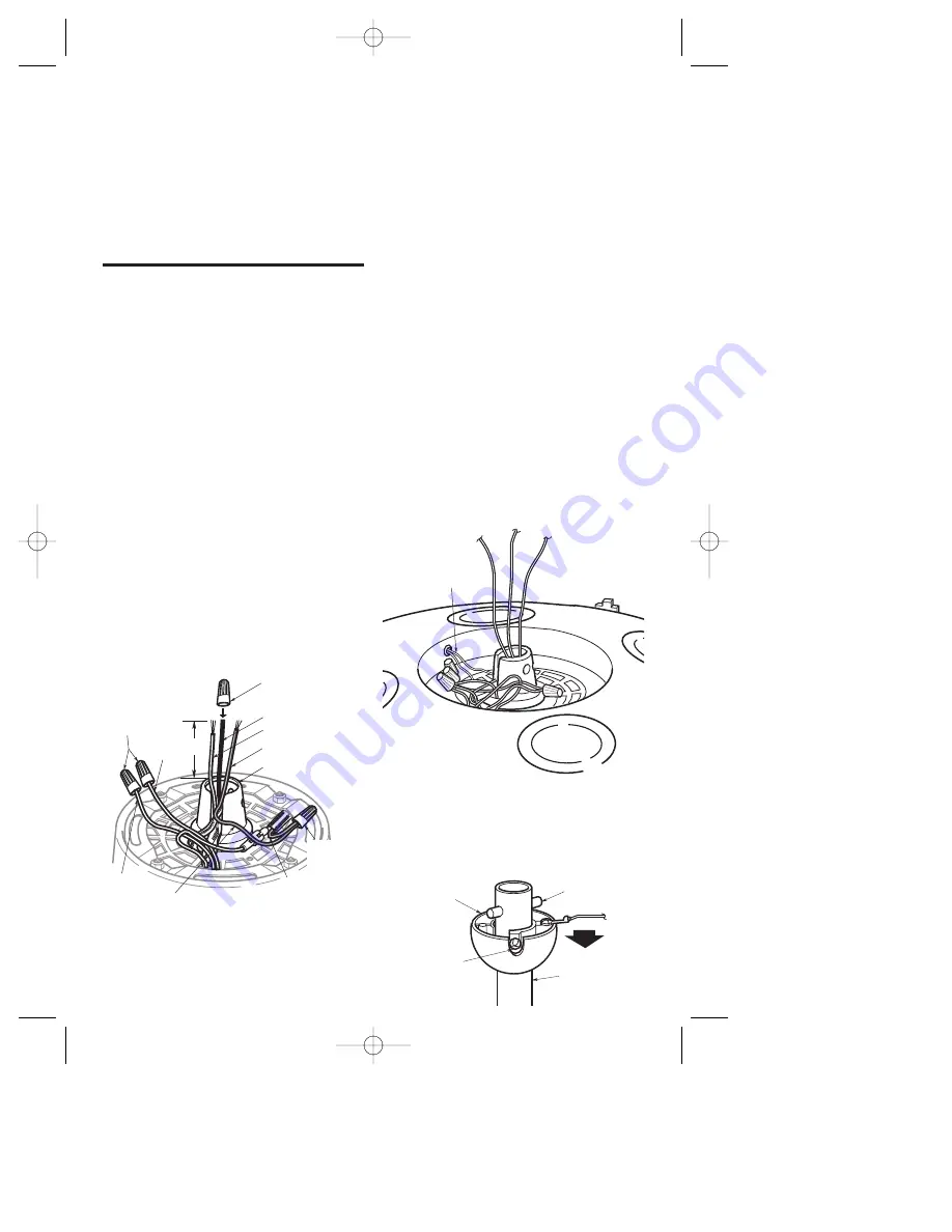
1. Remove the wire connectors from the

red and brown wires. Cut the white,
blue and black wires about 3" above
the motor coupling (Figure 1). Strip
insulation 1/2" from end of white, blue,
red and brown wires. Install a wire
connector on the black wire; this wire
will not be used.

YELLOW  WIRE FROM MOTOR 
COUPLING (See NOTE 3)

BROWN
WIRE

RED WIRE

YELLOW WIRE
FROM UPLIGHT
(See NOTE 3)

REMOVE WIRE 
CONNECTORS 
FROM RED AND 
BROWN WIRES 
(See NOTE 1)

3"

BLUE WIRE

BLACK WIRE
WHITE WIRE

CAP BLACK WIRE 
USING A WIRE 
CONNECTOR

REMOVE 
WIRE 
CONNECTOR 

MOTOR COUPLING

Figure 1

NOTE 2: On Model CF1, CF2400, and
CF2800 Series Ceiling Fans, the red
and brown wires from the motor are
connected to red and brown wires from
the reversing switch. Remove the wire
connectors and separate these wires.
Using wire connectors, cap the red and
brown wires from the reversing switch;
these wires will not be used.

NOTE 3: If your ceiling fan does not
have a built-in uplight, these yellow
wires will not be present.

2. Remove the wire connector (Figure 1)

from the yellow wires (See NOTE 3).
Separate the yellow wires, and cap the
yellow wire coming from the motor
coupling.

NOTE 4: On early Model CF2400 Series
Ceiling Fans, cut the orange wire
midway between the motor coupling
and the housing (Figure 2). Cap the
orange wire from the motor coupling
using a wire connector. The orange
wire from the housing will get
connected to the uplight yellow wire in
Step 6.

3. Loosen the setscrew in the hanger ball,

slide the ball down the hanger pipe,
and remove the clevis pin. Then slide
the hanger ball off the hanger pipe
(Figure 3). Retain all parts.

DOWNROD

CLEVIS PIN

SETSCREW

HANGER
BALL

Figure 3

ORANGE WIRE 
(See NOTE 3)

Figure 2

BP7253-2  4/28/06  11:58 AM  Page 3

Summary of Contents for SR330

Page 1: ...F2300 1 CF2400 1 CF2454 2 CF2500 1 CF2600 2 CF2650 0 CF2675 1 CF3500 0 CF3900 1 CF4500 4 CF4600 0 and CF4800 3 Off On Up Down Lights Select Fan Sleep Flow Security Model SW350 Wall Control Lights Fan Select Airflow Sleep Security Winter Fan Low Down Light Fan High Up Light Air DN Air UP Model SR330 Remote Control Model SW375 Receiver NOTE The SW350 and SR330 controls must be used with a SW375 rece...

Page 2: ...n tested and found to comply with the limits for a class B digital device pursuant to part 15 of the FCC Rules These limits are designed to provide reasonable protection against harmful interference in a residential installation This equipment generates uses and can radiate radio frequency energy and if not installed and used in accordance with the instructions may cause harmful interference to ra...

Page 3: ...T See NOTE 3 REMOVE WIRE CONNECTORS FROM RED AND BROWN WIRES See NOTE 1 3 BLUE WIRE BLACK WIRE WHITE WIRE CAP BLACK WIRE USING A WIRE CONNECTOR REMOVE WIRE CONNECTOR MOTOR COUPLING Figure 1 NOTE 2 On Model CF1 CF2400 and CF2800 Series Ceiling Fans the red and brown wires from the motor are connected to red and brown wires from the reversing switch Remove the wire connectors and separate these wire...

Page 4: ...ellow wire supplied with fans containing built in Uplights through the hanger pipe until they extend about 4 out of the pipe Figure 4 5 Cut the harness wires approximately 3 from the end of the pipe Strip insulation 1 2 from end of wires 6 Using wiring connectors supplied connect the white red yellow blue and brown wires of the wiring harness to the white red yellow orange wire for early CF2400 Mo...

Page 5: ...ed with steps 11 through 19 below 11 Position the ceiling cover over the hanger pipe Figure 8 Be sure the cover is oriented correctly with the large opening at the top 12 Install the hanger ball on the hanger pipe as follows Route the wiring harness connectors through the hanger ball and slide the hanger ball over the hanger pipe Install the pin through the holes at the top of the hanger pipe and ...

Page 6: ... screws from existing switches Pull switches out from wall boxes and determine which wall box contains the hot lead and which wall box contains the load wire Also identify traveler wire s which are common to both wall boxes 16 Connect the black wire from the wiring harness to the black hot supply wire Figure 5 Connect the white wire from the wiring harness to the white neutral supply wiring Connec...

Page 7: ... already connected to the black wire in the other wall box Secure with wire connectors supplied 7 STANDARD WIRING FOR EXISTING 3 WAY CONTROLS HOT BLK TRAVELER WIRES BLACK LOAD EXISTING WALL CONTROL SW350 WALL CONTROL BLK BLK BLK BLACK LOAD TRAVELER WIRES HOT BLK Off On Up Down Lights Fan Sleep Off On Up Down Lights Fan Sleep 3 WAY WIRING DIAGRAM RETROFIT Figure 13 Do not connect any neutral white ...

Page 8: ...e SW375 Receiver If any changes have been made to the fan or light functions using the SW350 Wall Control those changes are not indicated on the remote LCD display When the SR330 Remote Control buttons are pressed the fan and light functions change to the LCD display settings Off On Up Down Lights Fan Sleep YELLOW WIRE TO YELLOW WIRE Built in Up Light Only BLUE WIRE TO BLUE WIRE SW375 RECEIVER WIR...

Page 9: ...he Up Down arrow buttons without disabling the Sleep function The fan will continue to decrease by one speed every 60 minutes until the fan is on low speed NOTE The Code Learning Procedure must be performed before the wall control will operate the fan or light NOTE An audible tone will be heard from the receiver whenever any of the fan light or any other function buttons are pressed A LIGHT Functi...

Page 10: ...ed as follows The uplight and downlight can be operated independently Press the Select button to change between downlight uplight fan operation When the downlight symbol glows on the LCD panel you have control of the down light When the uplight symbol glows on the LCD panel you have control of the uplight NOTE The Light On Off button features a soft on soft off feature that ramps the downlight dow...

Page 11: ...t setting The Sleep icon will be seen on the LCD panel indicating Sleep mode If the fan is already on then it will decrease from its current setting If the fan is off it will start from fan setting 3 medium and decrease from there Once the Sleep function is activated the fan speed can be increased or lowered using the Up Down Arrow buttons without disabling the Sleep function The fan will continue...

Page 12: ...amage in transit since we will not be responsible for any such damage What Is Not Covered This warranty also does not cover any defects malfunctions or failures caused by Repairs by persons not authorized by Emerson Electric Co Use of parts or accessories not authorized by Emerson Electric Co Mishandling improper installation modifications or damage to your remote control while in your possession ...

Reviews: