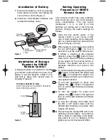
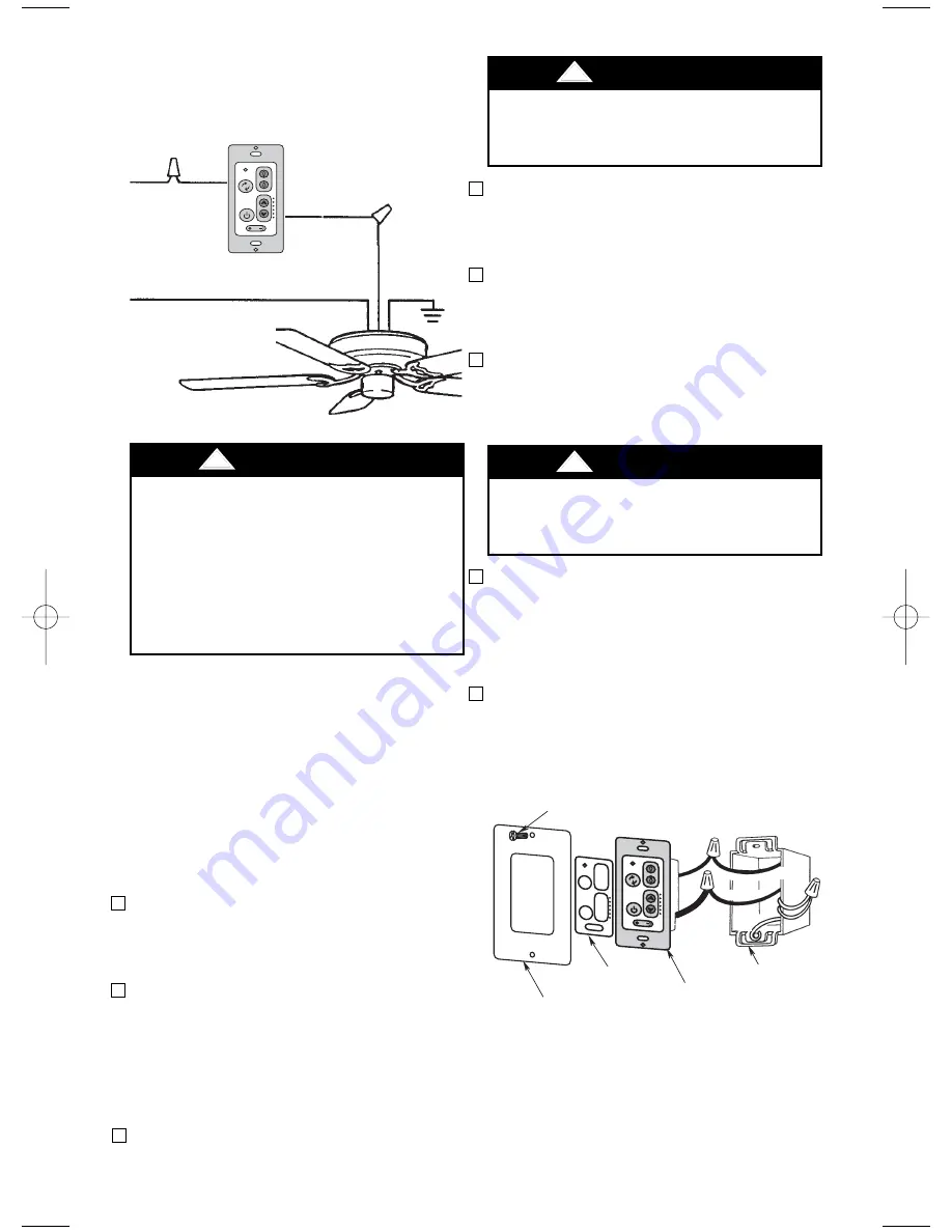
Installation of Wall Control
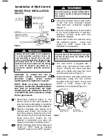
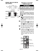
SINGLE-POLE INSTALLATION
(Figure 6)
1.
Disconnect electrical power to the
branch circuit at the circuit breaker or
fuse box before attempting to install the
ceiling fan wall control into the outlet box.
2.
Remove faceplate and screws from
existing wall control. Pull control out
from the wall box. Determine the “hot”
wire and the “load” wire and disconnect
these wires from control. Do not
attempt to disconnect any wires not
already connected to existing control.
3.
Before installing wall control, place wall
control in “OFF” mode by pushing
“ON/OFF” switch to the “OFF” position.
EMERSON
®
HI
MED
LOW
FAN OFF
LIGHT
ON
OFF
SW605 FAN/LIGHT
WALL CONTROL
HOT
BLK
NEUTRAL
BLACK
GROUND
LOAD
BLACK
RECEIVER LOCATED
WITHIN THE CEILING
COVER
Figure 6
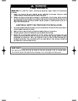
Turning off wall switch is not sufficient.
To avoid possible electrical shock, be
sure electricity is turned off at the main
fuse or circuit breaker box before wiring.
All wiring must be in accordance with
National and Local codes and the ceiling
fan must be properly grounded as a
precaution against possible electrical
shock.
!
WARNING
CAUTION: To reduce the risk of
electrical shock, disconnect the
electrical supply circuit before
installing the fan, light kit or receiver.
NOTE: Make all wiring connections
using wire connectors (supplied). Make
sure that all connections are tight,
including ground, and that no bare wire
is visible at the wire connectors, except
for the ground wire.
7
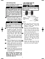
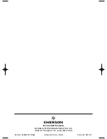
7.
The wall control is supplied with a
white, ivory, and almond color switch
covers. Choose the finish that best
suits your needs and snap the cover
onto the wall control (Figure 7).
8.
Install decorator wall plate (purchased
separately) using the two screws
provided with wall plate. Leave wall
control in “OFF” mode until fan
installation is completed (Figure 7).
Do not connect any neutral (white) wire to
this control. Incorrect wiring will damage
this control.
!
WARNING
Check to see that all connections are tight
and that no bare wires are visible at the
wire connectors.
!
WARNING
FAN/LIGHT
WALL CONTROL
WALL
BOX
BLA
CK
BL
K
HOT
SWITCH
COVER
DECORATIVE
WALL PLATE
SCREWS (2)
TO 1
20VAC SOURC
E
TO LOAD
G
RO
UN
D
Figure 7
4.
Connect one black wire of wall control
to the “hot” wire. Securely connect
wires with wire connectors supplied
(Figure 7).
5.
Connect one black wire of wall switch
to the “load” (black) wire in wall box.
Securely connect wires with wire
connector supplied.
6.
Screw wall control into wall box using
the supplied screws. Leave wall
control in “OFF” mode until fan
installation is completed.
BP7417 SR600 SR650 SW605 12/15/09 8:29 PM Page 7


