15
emersonfans.com
Please contact 1-800-654-3545 for further assistance
U.L. Model No.: CF850
6. Final Assembly
(continued)
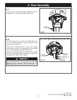
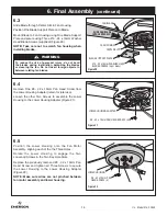
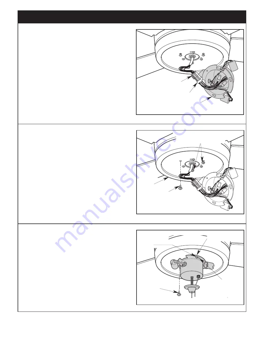
6.6
Engage the Light Kit Assembly Connector to the Motor
Connector (Figure 23) .
The Two Connectors are Keyed and Color-Coded and
must be mated correctly (color-to-color) before they can
be engaged . Make sure the Connector Latch closes
properly .
NOTE: Make sure all wires and connector are
tucked under the light kit assembly and not
pinched between light kit assembly and lower
housing.
LIGHT KIT ASSEMBLY
LIGHT KIT ASSEMBLY WIRE
CONNECTOR
MOTOR HOUSING WIRE
CONNECTOR
Figure 23
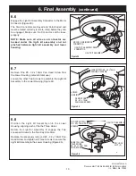
6.7
Remove One #8 - 32 x 10mm Pan Head Screw from
the Lower Housing (retain for later use) .
Loosen the other Two Screws to assemble the Light Kit
Assembly to the Lower Housing (Figure 24) .
REMOVE ONE
#8 - 32 x 10mm
PAN HEAD SCREW
LOWER
HOUSING
LOOSEN TWO #8 - 32 x 10mm
PAN HEAD SCREWS
Figure 24
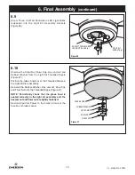
6.8
Position the Light Kit Assembly onto the Lower
Housing, aligning each of the the Three Holes .
Rotate the Light Kit Assembly to engage the Two
Loosened Screws in the Two Key Hole Slots .
Replace the previously removed #8 - 32 x 10mm Pan
Head Screw and tighten all Three Screws to secure the
Light Kit Assembly to the Lower Housing (Figure 25) .
REINSTALL AND
TIGHTEN ONE
#8 - 32 x 10mm PAN
HEAD SCREW
KEY HOLE
SLOT (2)
RETIGHTEN TWO
#8 - 32 x 10mm PAN HEAD
SCREWS
LIGHT KIT ASSEMBLY
Figure 25
Summary of Contents for SUMMERHAVEN LED CF850GES01
Page 22: ...22 U L Model No CF850 Notes ...


