background image

18


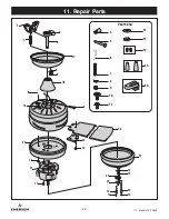
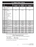
U.L.  Model No.: CF850

This product is designed to use only those parts 

supplied with this product and/or any accessories 

designated specifically for use with this product 

by Emerson Electric Co. Substitution of parts or 

accessories not designated for use with this product 

by Emerson Electric Co. could result in personal injury 

or property damage.


WARNING

!

See your local Emerson dealer, www .emersonfans .com 

or the Emerson Ceiling Fan catalog for these 

accessories:
·  Ceiling Fan Wall Controls
·  Downrod Extension Kits
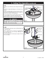
8. Accessories

9. Energy Efficient Use of Ceiling Fans

The use of any other control not specifically approved 

for this fan could result in fire, shock and personal 

injury.


WARNING

!

Do not use water when cleaning your ceiling fan. 

It could damage the motor or the blades and create the 

possibility of an electrical shock.


WARNING

!

IMPORTANT CARE INSTRUCTIONS 

for your Ceiling Fan

Periodic cleaning of your new ceiling fan is the only 

maintenance that is needed .
When cleaning, use only a soft brush or lint free cloth to 

avoid scratching the finish .
Abrasive cleaning agents are not required and should 

be avoided to prevent damage to finish .

7. Maintenance

Ceiling fan performance and energy savings rely 

heavily on the proper installation and use of the 

ceiling fan . Here are a few tips to ensure quality and 

product performance .
Choosing the Appropriate Mounting Location.  

Ceiling fans should be installed, or mounted, in the 

middle of the room and at least 7 feet above the floor 

and 18 inches from the walls . If ceiling height allows, 

install the fan 8 - 9 feet above the floor for optimal 

airflow . Consult your Emerson Retailer for optional 

mounting accessories .

Using the Ceiling Fan Year Round.  In the summer, 

use the ceiling fan in the counter-clockwise direction . 

The airflow produced by the ceiling fan creates a 

wind-chill effect, making you “feel” cooler . Select a 

fan speed that provides a comfortable breeze, lower 

speeds consume less energy . In the winter, reverse 

the motor and operate the ceiling fan at low speed in 

the clockwise direction . This produces a gentle updraft, 

which forces warm air near the ceiling down into the 

occupied space . Remember to adjust your thermostat 

when using your ceiling fan - additional energy and 

dollar savings could be realized with this simple step! 
Turn Off When Not in the Room.  Ceiling fans cool 

people, not rooms . If the room is unoccupied, turn off 

the ceiling fan to save energy .

Summary of Contents for SUMMERHAVEN LED CF850GES01

Page 1: ...ocation Ceiling Fan Owner s Manual Questions problems missing parts Before returning to the store call Emerson Electric Customer Service 8 a m 6 p m Eastern Monday Friday 1 800 654 3545 www emersonfans com Net Weight 23 8 Lbs INDOOR OUTDOOR CF850SW01 Satin White CF850GES01 Golden Espresso CF850VNB01 Venetian Bronze Model Numbers TM ...

Page 2: ...ommonly used for support of light fixtures are not acceptable for fan support and may need to be replaced Consult a qualified electrician if in doubt 4 The downrod furnished with the fan provides the minimum recommended floor to fan blade clearance for an 8 foot ceiling 5 The fan must be mounted with the fan blades at least 7 feet from the floor to prevent accidental contact with the fan blades 6 ...

Page 3: ...from being lost If any parts are missing call 1 800 654 3545 for replacement parts before proceeding 1 2 Remove the Fan Motor Assembly from the protective plastic bag Place the Fan Assembly into the upper styrofoam with the top of the Motor facing up The upper styrofoam serves as a holder for the Fan during the first stages of assembly PACKAGE CONTENTS 1 5 4 6 1 1 1 3 2 7 8 9 10 Part Description Q...

Page 4: ... 1 800 654 3545 if you have any questions about installation and operation of this Ceiling Fan Your new Ceiling Fan will require a grounded electrical supply line of 120 Volts AC 60 Hz 15 Amp Circuit To reduce the risk of fire electric shock or personal injury mount fan to outlet box marked Acceptable for Fan Support of 22 7 kg 50 lbs or less and use screws supplied with outlet box Most outlet box...

Page 5: ...osening the Set Screw in the Hanger Ball until the Ball falls freely down the Downrod Figure 2 Remove the Pin from the Downrod then remove the Hanger Ball Retain the Pin and Hanger Ball for reinstallation in Step 3 18 NOTE Do not loosen the screw holding the green ground wire PHILLIPS HEAD SET SCREW LOOSENED HANGER BALL 4 5 DOWNROD PIN GREEN GROUND WIRE Figure 2 THREE 80 MOTOR WIRES UNTWISTED 4 5 ...

Page 6: ... with the Two Holes in the Motor Coupler Figure 4 CLEVIS PIN HAIRPIN CLIP HAIRPIN CLIP CLEVIS PIN MOTOR COUPLER Figure 5 3 5 Install the Clevis Pin and secure with the Hairpin Clip Figure 5 The Clevis Pin must go through the Motor Coupler Holes It is critical that the Clevis Pin in the Motor Coupler is properly installed and securely tightened It is critical that the clevis pin in the motor couple...

Page 7: ...ly continued 4 5 DOWNROD GROMMET COUPLER COVER Figure 7 3 7 Make sure the Grommet is properly installed in the Motor Coupler Cover then slide the Motor Coupler Cover on the Downrod until it rests on the Motor Housing Be sure the Motor Coupler Cover is oriented correctly Figure 7 CEILING COVER 4 5 DOWNROD Figure 8 3 8 Place the Ceiling Cover over the Downrod Be sure the Ceiling Cover is oriented co...

Page 8: ...ew in the Hanger Ball NOTE A loose set screw could create fan wobble It is critical that the pin in the hanger ball is properly installed and the set screw securely tightened Failure to verify that the pin and set screw are properly installed could result in the fan falling WARNING 3 Ceiling Fan Assembly continued BLACK WIRE 6 TO 9 INCHES BLUE WIRE WHITE WIRE HANGER BALL 1 2 INCH 3 10 The Fan come...

Page 9: ...0 lbs or less and use screws supplied with outlet box Most outlet boxes commonly used for support of light fixtures are not acceptable for fan support and may need to be replaced Consult a qualified electrician if in doubt WARNING 4 1 Securely attach the Hanger Bracket to the Outlet Box using the Two Screws supplied with the Outlet Box Figure 12 Hanger bracket must seat firmly against outlet box I...

Page 10: ...T BOX HANGER BRACKET HANGER BALL DOWNROD ASSEMBLY NOTE CEILING COVER SUPPL Y WIRES AND FAN WIRES OMITTED FOR CLARITY HANGER BRACKET HANGER BALL HANGER BALL GROOVE ANTI ROTATION TAB Figure 13 4 How to Hang Your Ceiling Fan continued 4 2 Carefully lift the Fan and seat the Hanger Ball Downrod Assembly into the Hanger Bracket that was just attached to the Outlet Box Figure 13 Be sure the Groove in th...

Page 11: ... for wiring Securely connect the Fan Motor White Wire to the Supply White neutral Wire using Wire Connector supplied Figure 15 5 How to Wire Your Ceiling Fan To avoid possible electrical shock be sure electricity is turned off at the main fuse box before wiring NOTE If you are not sure if the outlet box is grounded contact a licensed electrician for advice as it must be grounded for safe operation...

Page 12: ...EEN WIRES Figure 17 5 4 After Connections have been made turn Wires upward and carefully push Wires into the Outlet Box with the White and Green Wires on one side of the Outlet Box and position the Black Black Blue Wires on the other side of the Outlet Box Figure 17 Check to see that all connections are tight including ground and that no bare wire is visible at the wire connectors except for the g...

Page 13: ...g cover and the ceiling WARNING 6 2 Lift the Ceiling Cover up to the Threaded Studs and turn until Studs protrude through the Holes in the Ceiling Cover Figure 19 Secure the Ceiling Cover in place by sliding Lockwashers over the Threaded Studs and installing the Two Knurled Knobs supplied Figure 19 Tighten the Knurled Knobs securely until the Ceiling Cover fits snugly against the Ceiling and the H...

Page 14: ...ning the fan Do not insert foreign objects in between rotating fan blades WARNING 6 4 Remove One 8 32 x 10mm Pan Head Screw from the Lower Housing Adapter retain for later use Loosen the other Two Screws to assemble the Lower Housing to the Lower Housing Adapter Figure 21 8 32 x 10mm PAN HEAD SCREW 3 LOWER HOUSING ADAPTER Figure 21 6 5 Position the Lower Housing onto the Fan Motor Assembly alignin...

Page 15: ...ECTOR Figure 23 6 7 Remove One 8 32 x 10mm Pan Head Screw from the Lower Housing retain for later use Loosen the other Two Screws to assemble the Light Kit Assembly to the Lower Housing Figure 24 REMOVE ONE 8 32 x 10mm PAN HEAD SCREW LOWER HOUSING LOOSEN TWO 8 32 x 10mm PAN HEAD SCREWS Figure 24 6 8 Position the Light Kit Assembly onto the Lower Housing aligning each of the the Three Holes Rotate ...

Page 16: ...ht Kit Threaded Nipple Figure 27 Position the Glass Shade over the Threaded Nipple in the Light Kit Plate Assembly Reinstall the Rubber Washer Hex Jamnut Bowl Cap and Finial Nut onto the Threaded Nipple Figure 27 NOTE Periodically check that the glass bowl is seated correctly in the light kit assembly and the hex jamnut and finial nut are tightly fastened Restore Electrical Power to the branch cir...

Page 17: ...ERSING SWITCH FAN MOTOR ASSEMBLY Figure 29 6 11 Check the operation of the Fan by gently pulling on the Pull Chain Switch off center pull chain Cut the 3 speed switch pull chain to a desired length optional Connect the Small Wood Pendant supplied to the 3 speed switch center Pull Chain by sliding the Wood Pendant small hole first onto the Pull Chain Figure 28 Attach the Chain Coupler to the end of...

Page 18: ...be avoided to prevent damage to finish 7 Maintenance Ceiling fan performance and energy savings rely heavily on the proper installation and use of the ceiling fan Here are a few tips to ensure quality and product performance Choosing the Appropriate Mounting Location Ceiling fans should be installed or mounted in the middle of the room and at least 7 feet above the floor and 18 inches from the wal...

Page 19: ...e the flanges to the motor hub are tight 4 Wire connectors inside switch housing 4 Check to make sure wire connectors in switch rattling housing are not rattling against each other or against the interior wall of the switch housing 5 Screws holding blades to flanges are 5 Tighten screws securely loose 3 Fan wobbles 1 Set screw in motor coupler is loose 1 Tighten both set screws securely in the mot...

Page 20: ...1 2 3 7 9 17 PARTS BAG 4 5 10 11 18 21 11 11 5 26 19 20 6 25 10 22 24 15 14 13 12 23 15 14 6 8 9 7 12 13 14 15 16 8 20 U L Model No CF850 11 Repair Parts ...

Page 21: ... 4 Connector Wire 12 Ga 3 5 Pin Clevis 1 6 Clip Hairpin 1 7 Stud Threaded 8 32 x 1 1 4 2 8 Lockwasher External Tooth 8 2 9 Knob Knurled 8 32 2 10 Screws Washer Head Blade 10 24 x 15mm 16 11 Screw Pan Head 8 32 x 10mm 1 12 Rubber Washer 1 13 Hex Jam Nut 1 14 Pull Chain Coupler 2 15 Wood Pendants Large Small 2 16 Kit Balancing 1 17 Ceiling Cover 1 764167 GES 764167 SW 764167 VNB 18 Motor Coupler Cov...

Page 22: ...22 U L Model No CF850 Notes ...

Page 23: ...cessory caused by normal wear and tear rather than due to defects in materials or workmanship Loss or damage resulting from conditions beyond our reasonable control including without limitation unforeseeable operating environmental conditions repairs not made at Our factory or authorized service center use of parts or accessories not provided to You as part of this warranty by Our factory or autho...

Page 24: ...MERSON ELECTRIC CO 8100 W Florissant St Louis MO 63136 Part No F40BP74430001 Form No BP7549 1 Revision 190129 U L Model No CF850 Printed in China 01 19 SERIAL NUMBER DATE CODE The serial number of this fan can be found on the nameplate on top of the fan housing The date code can be found on the carton and on top of the fan housing stamped in ink on a white label You should record this data above a...

Reviews: