background image

Maintenance


 WARNING

To avoid personal injury, property 

damage or equipment damage caused 

by sudden release of pressure or 

explosion of accumulated gas, do 

not attempt any maintenance or 

disassembly without first isolating the 

pilot from system pressure and relieving 

all internal pressure from the pilot.
Pilots that have been disassembled 

for repair must be tested for proper 

operation before being returned to 

service. Only parts manufactured by 

Emerson should be used for repairing 

this pilot.
Due to normal wear or damage that may 

occur from external sources, this pilot 

should be inspected and maintained 

periodically. The frequency of inspection 

and replacement of parts depends upon 

the severity of service conditions or the 

requirement of local, state and federal 

rules and regulations.


 CAUTION

Do not, under any circumstances, loosen 

the bolts on the diaphragm chamber of 

the Type T124 or T134 Temperature Pilot 

or attempt to dismantle the thermostat 

element. The system is filled with 

volatile fluid which, if lost, will render the 

pilot inoperative.

Dismantling

1.  Remove diaphragm nuts (key 4) and lift off top 

works and diaphragms.

2.  Remove the blind flange bolts (key 7) and 

take off the blind flange (key 26). Remove the 

screen (key 46) and gasket (key 45 ).

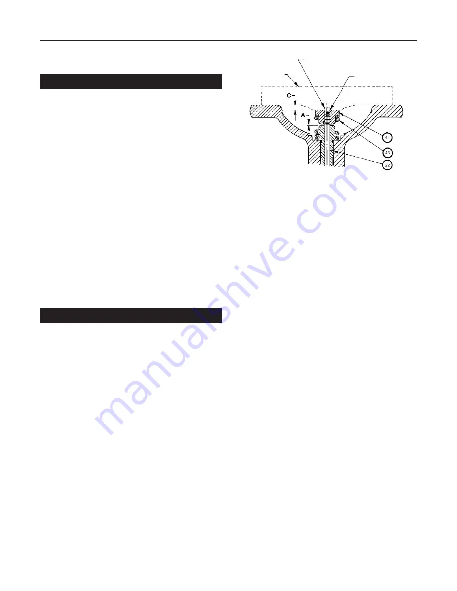
3.  Hold the pusher plate (key 41) with a socket 

wrench and remove stem nuts (key 25). The disk 

(key 24) will drop off.

4.  Lift out the stem (key 22) and valve spring 

(key 43).

Assembly

1.  Reassemble the pilot in the reverse of the 

Dismantling procedure.

2.  Ensure that diaphragm screw (key 37) and cowl 

bracket (key 19) are centered on diaphragm flange 

of the pilot body (key 44). Misalignment can cause 

erratic performance.

3.  When replacing diaphragms, apply sealing 

compound (High pressure, high-temperature 

sealant) sparingly to the shoulder of the diaphragm 

screw (key 37). For steel pilot only, apply sealing 

compound to the diaphragm flange of the 

pilot body.

Seat, Disk and Stem Replacement

1.  Examine the seat and disk sealing surfaces for 

nicks or other signs of damage by pipeline debris. 

Replace the sealing surfaces if damaged.

2.  When seat or disk is replaced, ensure that the 

sealing surfaces are lapped. After the sealing 

surfaces are lapped in, disassemble and clean 

all parts.

Note

Lap sparingly using 500 grit lapping 

compound and light pressure. Heavy 

grinding may cause galling, wide sealing 

surfaces and a grooved disk, all of which 

tend to produce leakage.

Figure 5

. Travel Setting

GAGE

PRICK PUNCH

STEM PROJECTION "B" TO BE 

REMOVED AS PER INSTRUCTIONS

6

Types T124 and T134

Summary of Contents for T124

Page 1: ... and T134 Introduction Scope of the Manual This manual provides instructions for installation maintenance and parts information for the Types T124 and T134 temperature pilot Product Description The steam pressure reducing valve and temperature regulator in a single pilot operated valve is a combination of Type T124 or T134 Pilot and a Type E or C Main Valve Steam pressure is modulated in proportio...

Page 2: ...g The pilot is opened by compressing the pressure limit spring When steam is turned on it flows to the pilot through the connecting nipple and union see Figure 2 At No 8B tee on the pilot outlet the flow divides One branch is connected to bleedport No 4A and the other to restriction elbow No 5A and the underside of the main valve diaphragm Bleedport No 4A restricts the flow builds pressure under t...

Page 3: ...ALVE STRAINER STEAM TRAP INITIAL PRESSURE TYPE ET124 OR ET134 TEMPERATURE REGULATOR DO NOT INSULATE BELOW THIS LINE Figure 3 Type T124 Tubing Bends Connection PILOT FLEXIBLE ARMORED TUBING TEMPERATURE ADJUSTING SPRING COWL BRACKET SET SCREW PRESSURE LIMIT SPRING DELIVERY PRESSURE ADJUSTMENT SCREW 1 4 CONTROL PIPE 1 4 UNION RESTRICTION BEND MAIN VALVE TYPE E OR E2 NO 4A BLEED PORT NO 8B TEE BLEED P...

Page 4: ...ately designed and supported to prevent extraordinary loads to the pressure equipment Planning 1 Locate the regulator in a horizontal pipe Provide a trap ahead of the regulator to prevent water hammer and erratic operation 2 Use a strainer to avoid damaging effects of scale and dirt in pipelines to protect the regulator 3 Provide a three valve bypass to facilitate inspection of the regulator witho...

Page 5: ...applied to the upper portion globe and flanges of the main valve Do not insulate the diaphragm chamber or any part of pilot See Figure 2 Start up and Setting WARNING The pilot may be handling hazardous fluids Only qualified personnel who are familiar with the installation should be permitted to install readjust inspect or maintain the pilot CAUTION Insulation may be applied to the pilot body only ...

Page 6: ... flange bolts key 7 and take off the blind flange key 26 Remove the screen key 46 and gasket key 45 3 Hold the pusher plate key 41 with a socket wrench and remove stem nuts key 25 The disk key 24 will drop off 4 Lift out the stem key 22 and valve spring key 43 Assembly 1 Reassemble the pilot in the reverse of the Dismantling procedure 2 Ensure that diaphragm screw key 37 and cowl bracket key 19 ar...

Page 7: ...n bulbs at this temperature during replacement process 2 Back off temperature adjusting wheel key 14 to within a turn or two of the barrel nut key 1 Back off pressure adjusting screw key 20 to remove all compression from spring This will allow temperature diaphragm plate key 7 to remain seated in correct alignment on balls key 10 after disengagement of thermostat assembly Unless pilot is upright b...

Page 8: ...ous heater outlet 4 Thermostat may be kinked or broken or have lost its fill Alternately warm and cool thermostat 10 F 12 C above and below its set point If thermostat is operative the pin between the lever and pressure diaphragm will become loose and snug as the temperature stem on opposite end of the lever moves up and down 5 Orifice in bleedport may be plugged 6 A lift of condensate to a hot we...

Page 9: ...el WAL04 04057 90 Composition Disk 303 Stainless steel WAL04 04060 00 24 Disk Standard 440 CH WAL04 01772 90 Composition Disk Brass Hycar WAL07 53512 00 25 Stem Nut Steel WAL05 02888 00 Brass WAL05 02886 00 26 Blind Flange Cast Iron WAL04 02151 00 Cast Steel WAL04 11678 00 27 Blind Flange Bolt Steel and Iron WAL05 04803 00 Steel and Steel WAL05 11720 00 28 Temperature Plate Center Ledloy WAL04 037...

Page 10: ... E F TYPE T134 SIDE VIEW FRONT VIEW Figure 6 Type T124 Assembly THERMOSTAT ASSEMBLY VARIES 1 8 NPT 10 Types T124 and T134 ...

Page 11: ...COMPOSITION DISK ADJUSTMENT INDICATOR Figure 7 Type T124 Options Assembly 11 Types T124 and T134 ...

Page 12: ...ding the products or services described herein or their use or applicability All sales are governed by our terms and conditions which are available upon request We reserve the right to modify or improve the designs or specifications of such products at any time without notice Emerson Electric Co does not assume responsibility for the selection use or maintenance of any product Responsibility for p...

Reviews: