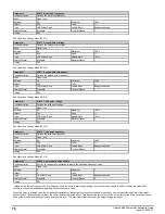
Parameter
05.081
Change to maximum drive switching frequency at low output current
Short description
Change to maximum drive switching frequency at low output current
Mode
Open
‑
loop
Minimum
0
Maximum
1
Default
0
Units
Type
1 Bit User Save
Update Rate
Background read
Display Format
Standard
Decimal Places
0
Coding
RW
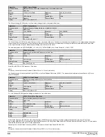
If the user has selected a maximum switching frequency in the range 2kHz to 6kHz, setting this parameter will cause the drive to switch to maximum switching
frequency at low output currents.
Swaps to 16kHz if the output current magnitude is less than 30% (Frame sizes 1-4) and 20% (Frame sizes 5 and above) of drive OI.AC level for a period
longer than 100ms.
Swaps back immediately if the output current magnitude increases above the defined levels by more than 5%.
The original switching frequency may still be under the control of the inverter thermal model. This feature is disabled if the thermal model or user has changed
the switching frequency within the last 10 seconds.
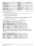
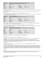
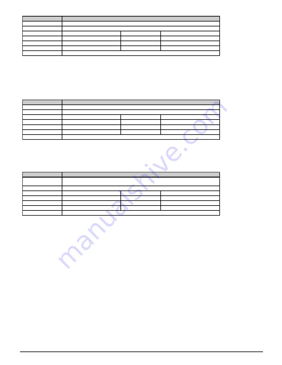
Parameter
05.083
Voltage Shelving Disable
Short description
Set to 1 to only measure the d.c. link voltage when the inverter is inactive
Mode
Open
‑
loop
Minimum
0
Maximum
1
Default
0
Units
Type
1 Bit User Save
Update Rate
Background read
Display Format
Standard
Decimal Places
0
Coding
RW
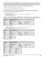
When this parameter is 1, the DC link voltage will only be measured when the inverter is inactive. The DC link voltage readings are filteredusing a 128ms
filter and the average value stored for use when the inverter becomes active.
This stored value is used instead of the actual measurement when the output voltage demand is converted to a modulation index.
This removes the dc bus voltage forward compensation. It will also remove the effects of “oscillation” experienced when the drive is supplied by an extremely
soft supply of through a high inductance filter.
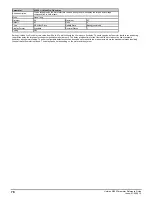
Parameter
05.084
Low Frequency Torque adjustment
Short description
Controls the boost level of the slip frequency when the output frequency is below one third of the rated
frequency.
Mode
Open
‑
loop
Minimum
0.0
Maximum
100.0
Default
0.0
Units
%
Type
16 Bit User Save
Update Rate
Background read
Display Format
Standard
Decimal Places
1
Coding
RW
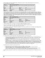
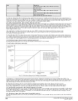
This parameter can be used to modify torque at low output frequencies in one of three different ways:
1) Slip boost
Used in resistor compensation (Ur) modes,
Open-loop Voltage Mode
(05.014) set to 0, 1, 3, and 4.
The slip frequency (see
Motor Rated Frequency
(05.006) is modified when the output frequency is below one third of the motor rated frequency to provide a
torque boost.
The modification consists of an addition to the
calculated slip frequency
controlled by the user parameter
Low Frequency Estimator Threshold,
Low Frequency Torque adjustment
(05.084) . The addition is equal to
Low Frequency Estimator Threshold, Low Frequency Torque adjustment
(05.084) x
calculated slip frequency
at zero Hz, falling linearly to 0.0% at one third of the motor rated frequency. e.g. if this parameter is set to 100%, the slip at 0Hz for
rated torque producing current
would be
rated slip + rated slip
or
2 x rated slip
.
2) Voltage boost
Used in resistor compensation (Ur) modes,
Open-loop Voltage Mode
(05.014) set to 0, 1, 3, & 4, and slip compensation has been disabled
(see
Motor Rated Frequency
(05.006) ).
The amount of stator resistor compensation is modified when the output frequency is below one tenth of the motor rated frequency to provide a torque boost.
The modification consists of an addition to the
calculated stator resistor compensation
controlled by the user parameter
Low Frequency Estimator Threshold,
Low Frequency Torque adjustment
(05.084) . The addition is equal to
Low Frequency Estimator Threshold, Low Frequency Torque adjustment
(05.084) x
calculated stator resistor compensation
at zero Hz falling linearly to 0 at one tenth of the motor rated frequency. e.g. if this parameter is set to 100%, the
stator
resistance compensation
at 0Hz would be
calculated stator resistor compensation
+ calculated stator resistor compensation
or
2 x calculated stator resistor
compensation
.
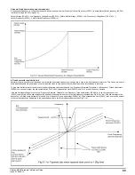
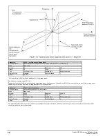
3) Slip taper
This feature is used in fixed boost tapered mode (
Open-loop Voltage Mode
(05.014) set to 6) to taper the slip limit back to zero at 0Hz. The taper start point is
defined as
Low Frequency Estimator Threshold, Low Frequency Torque adjustment
(05.084) x
Motor Rated Frequency
(05.006) / 100. See
Open-
loop Voltage Mode
(05.014) for a detailed explanation.
Unidrive M200 Parameter Reference Guide
Issue: 01.05.00.10
77
Summary of Contents for unidrive m200
Page 1: ...Parameter Reference Guide Unidrive M200 Open loop Mode Issue 01 05 00 10 ...
Page 30: ...30 Unidrive M200 Parameter Reference Guide Issue 01 05 00 10 ...
Page 83: ...Enable logic Unidrive M200 Parameter Reference Guide Issue 01 05 00 10 83 ...
Page 125: ...Unidrive M200 Parameter Reference Guide Issue 01 05 00 10 125 ...
Page 145: ...Unidrive M200 Parameter Reference Guide Issue 01 05 00 10 145 ...
Page 204: ...204 Unidrive M200 Parameter Reference Guide Issue 01 05 00 10 ...

