Parameter
structure
Keypad and
display
Parameter
x.00
Parameter
description format
Advanced parameter
descriptions
Macros
Serial comms
protocol
Electronic
nameplate
Performance RFC mode
Menus 15 to 17
SM-Uni Enc Pl
Unidrive SP Advanced User Guide
253
Issue Number: 10 www.controltechniques.com
5.17.1 SM-Universal Encoder Plus
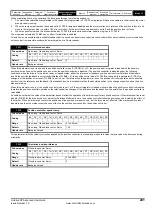
The Solutions Module checks for various errors as shown below.
Table 5-13 Solutions Module error status values for SM-Universal Encoder Plus
+These trips can be enabled/disabled by Pr
x.17
1. If the terminations are not enabled on the A, B or Z inputs the wire break system will not operate. (Note that as default the Z input terminations are
disabled to disable wire break detection on this input).
2. Phase error for a servo type encoder is to detect that the incremental pulses have been counted incorrectly. The error is detected if the
incremental position moves by 10
°
C with respect to the position defined by the UVW commutation signals. The trip is initiated if the error is
detected for 10 consecutive samples.
3. Phase error for SINCOS encoders with comms is detected by interrogating the encoder every second via comms to compare the incremental
position determined from the sine waves with the incremental position via comms. If the error is Š 10×C for 10 consecutive samples the trip is
initiated.
Encoder initialisation will occur when trips 1 to 8 are reset. This causes an encoder with comms to be re-initialized and auto-configuration to be
performed if selected.
It is important that a break in the connections between the drive and the position feedback device can be detected. This feature is provided either
directly or indirectly as listed.
When the drive is reset this parameter is cleared for the relevant Solutions Module
Error code
Encoders
Fault description
1
All
Power supply short circuit
2
Ab, Fd, Fr, Ab.SErvo, Fd.SErvo,
Fr.SErvo, SC.SErvo
+Hardware wire-break detect on A, B and Z inputs
(1)
SC, SC.HiPEr, SC.EndAt,
SSC.SSI, SC.SErvo
Software wire break detection on sine wave signals
3
Ab.SErvo, Fd.SErvo, Fr.SErvo,
SC.SErvo
+Phase error
(2)
SC.SErvo (both methods),
SC.HiPEr, SC.EndAt, SC.SSI,
SC.SErvo
+Sine/cosine phase error
(3)
4
SC.HiPEr, SC.EndAt, SC.SSI
Comms failure (timeout)
EndAt
Comms failure (timeout) or transfer time too long
SSI
Comms transfer time is too long
5
SC.HiPEr, SC.EndAt, EndAt
Checksum / CRC error or SSI not ready at start of position transfer (i.e. data input not one)
6
SC.HiPEr, SC.EndAt, EndAt
The encoder has indicated an error
SC.SSI, SSI
+Power supply failure
7
SC, SC.HiPEr, SC.EndAt,
SC.SSI, EndAt, SSI
Initialisation has failed due to a comms error.
8
SC.HiPEr, SC.EndAt, EndAt
Auto-configuration has been requested by changing Pr
x.18
. An initialisation will occur to perform
auto-configuration.
9
All
Thermistor trip, Over-temperature
10
All
Thermistor trip, Short circuit
11
SC, SC.HiPEr, SC.EndAt,
SC.SSI, SC.SErvo
Failure of analog position alignment during encoder initialisation
12
SC.HiPEr
The encoder type could not be identified during auto-configuration
13
SC.EndAt, EndAt
The number of encoder turns read from the encoder during auto-configuration is not a power of 2
14
SC.EndAt, EndAt
The number of bits defining the encoder position within a turn read from the encoder during auto-
configuration is too large.
15
SC.HiPEr, SC.EndAt, EndAt
The number of periods per revolution is either less than 2 or greater than 50000 when read or
calculated from the encoder data during auto-configuration.
16
SC.EndAt, EndAt
The number of comms bits per period are larger than 255.
74
All
The Solutions Module has overheated.
Summary of Contents for unidrive sp
Page 419: ......
Page 420: ...0471 0002 10 ...


