Menus 15 to 17
SM-Uni Enc Pl
Parameter
structure
Keypad and
display
Parameter
x.00
Parameter
description format
Advanced parameter
descriptions
Macros
Serial comms
protocol
Electronic
nameplate
Performance RFC mode
268
Unidrive SP Advanced User Guide
www.controltechniques.com Issue Number: 10
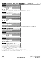
This position is taken from the position feedback device and is not affected by the marker or the freeze inputs.
Each time the marker becomes active the non-marker position values (Pr
x.29
to Pr
x.31
) are sampled and stored in Pr
x.32
to Pr
x.34
.
The freeze input to the SM Universal Encoder Plus can take the following forms
•
A 485 signal through the encoder marker simulation output pins
•
A 24V signal on the freeze 24V input
•
A signal on the internal drive and slot freeze line generated by another Solutions Module.
The selection of which mode used is dependent on the value of Pr
x.38
. The default is 1 that corresponds to only the 24V input to this Solutions
Module. The values correspond to the modes as described in the table below:
x.31
Non-marker reset fine position
RO
Uni
NC
PT
Ú
0 to 65535 (1/2
32
nds of a
revolution)
Ö
Update rate: 4ms write
x.32
Marker revolution counter
RO
Uni
NC
PT
Ú
0 to 65535 revolutions
Ö
Update rate: 4ms write
x.33
Marker position
RO
Uni
NC
PT
Ú
0 to 65535 (1/2
16
ths of a
revolution)
Ö
Update rate: 4ms write
x.34
Marker fine position
RO
Uni
NC
PT
Ú
0 to 65535 (1/2
32
nds of a
revolution)
Ö
Update rate: 4ms write
x.35
Freeze revolution counter
RO
Uni
NC
PT
Ú
0 to 65535 revolutions
Ö
Update rate: 250
μ
s write
x.36
Freeze position
RO
Uni
NC
PT
Ú
0 to 65535 (1/2
16
ths of a
revolution)
Ö
Update rate: 250
μ
s write
x.37
Freeze fine position
RO
Uni
NC
PT
Ú
0 to 65535 (1/2
32
nds of a
revolution)
Ö
Update rate: 250
μ
s write
x.38
Freeze input mode/ Marker output select
RW
Uni
US
Ú
0 to 7
Ö
1
Update rate: Background read
Summary of Contents for unidrive sp
Page 419: ......
Page 420: ...0471 0002 10 ...


