12 – 3
Section 12
•
Service Options
Vission 20/20 • Operation and Service Manual • Emerson • 35391SC 2.7
Liquid Injection # 1:
• Activates the output assigned to the liquid injection
solenoid. The output is connected on terminal 25
and is the 5th LED on card 2.
Liquid Injection # 2:
• Activates the output assigned to the liquid injection
solenoid. The output is connected on terminal 26
and is the 6th LED on card 2.
Remote Enabled:
• Activates the output assigned to notify a central con-
trol system of the Vission 20/20 running status. The
output is connected to terminal 27 and is the 7th LED
on card 2.
Shunt Trip:
• Activates the output during a false start condition
when the emergency stop timer has expired. This
output could be wired to a breaker with a shunt trip
that feeds power to a starter to force a shutdown.
The output is connected to terminal 28 and is the 8th
LED on card 2.
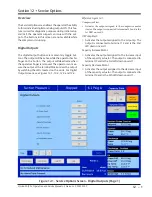
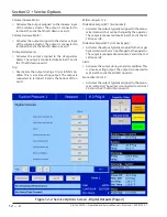
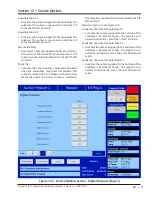
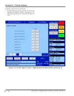
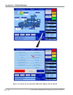
Reference Figure 12-3 and Figure 12-4.
Condenser / Remote Oil Cooler Step # 1:
• Activates the output assigned to the 1st step of the
Condenser / Remote Oil Cooler. The output is con-
nected to terminal 41 and is the 1st LED on card 4.
Condenser / Remote Oil Cooler Step # 2:
• Activates the output assigned to the 2nd step of the
Condenser / Remote Oil Cooler. The output is con-
nected to terminal 42 and is the 2nd LED down on
card 4.
Condenser / Remote Oil Cooler Step # 3:
• Activates the output assigned to the 3rd step of the
Condenser / Remote Oil Cooler. The output is con-
nected to terminal 43 and is the 3rd LED down on
card 4.
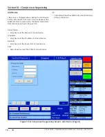
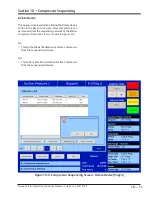
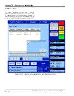
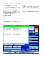
Figure 12-3. Service Options Screen - Digital Outputs (Page 3)
Summary of Contents for Vilter Vission 20/20
Page 1: ...Vission 20 20TM Micro controller Operation and service manual Version 2 7 ...
Page 2: ......
Page 4: ......
Page 220: ...B 2 Blank Vission 20 20 Operation and Service Manual Emerson 35391SC 2 7 ...
Page 300: ...D 2 Blank Vission 20 20 Operation and Service Manual Emerson 35391SC 2 6 ...
Page 336: ......
Page 337: ......

