B - 31
Appendix B
•
Vission 20/20 Application Procedures
Vission 20/20 • Operation and Service Manual • Emerson • 35391SC 2.7
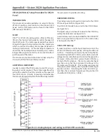
With the above setting, the response of the Aux1: Chiller
Level 4,20 Output is seen to be;
% Level Input
Aux1 Analog Output
50 %
=
4 ma
(fully closed position)
45 %
=
8 ma
40 %
=
12 ma
35 %
-
16 ma
30 %
=
20 ma (fully open position)
So a 20 % change in vessel level will cause the positioning
valve to go from a closed position to fully open position.
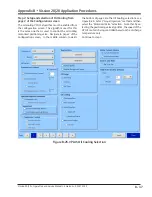
Decreasing the gain (P term) to 12.5 (by half) – will de-
crease the output sensitivity to a input change. The po-
sitioning valve will be stroked from closed to full open
position over a larger swing in vessel level. When you de-
crease the gain by half, then the 4-20ma output signal to
the positioning valve is applied over an input range that
is doubled;
% Level Input
Aux1 Analog Output
50 %
=
4 ma
40 %
=
8 ma
30 %
=
12 ma
20 %
=
16 ma
10 %
=
20 ma
Now a 40 % change in vessel level will cause the posi-
tioning valve to go from a closed position to fully open
position.
CONDENSER LEVEL CONTROL
Suppose we are trying to maintain a level of liquid in a
condenser. The condenser has a sump, and as the level
in the sump increases, we want to stroke a positioning
valve “more open” ( to allow more liquid refrigerant to
drain) thereby decreasing the amount of liquid in the
condenser sump.
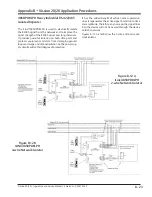
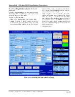
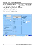
Reference the previous page. On the right side is the
setup for the condenser PID control. The setup is almost
the same with the exception that the trigger condition is
selected so that it goes true when the chiller level rises
above the setpoint, only then will the auxiliary analog
output control be enabled. In the above example, when
the chiller level is below 50%, the positioning valve will
be fully closed. As it rises above 50%, then the position-
ing valve will begin to open.
ANALOG OUTPUT SETUP FOR VESSEL LEVEL
CONTROL – PROPORTIONAL LEVEL CONTROL
Setting up the vessel level control using proportional
control allows you to define the exact percent opening
of the positioning valve based on the vessel level input
signal. This mode of operation for level control is not
as common since the valve opening is in direct propor-
tion to the defined input range, and doesn’t consider a
“setpoint” or “error from setpoint”. It simply moves the
positioning valve in direct relation to the defined level
input signal. This requires a lot of testing to know what
the correct input and output range is needed to achieve
a desired level.
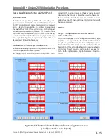
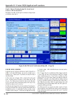
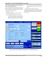
You can define an input range to cover the entire 0-100%
input span, or you can define a partial range – for in
-
stance 0 to 50%, see Figure B-21. The output can be the
full 4-20ma output range, or a partial range (for instance
12 to 20 ma). The input and output ranges are com-
pletely flexible. In addition, you can define an Inverse
output. The proportional control on the left is setup
such that for a 0 to 100% input, the respective output
ranges 20 ma to 4 ma (inverse acting output).
Summary of Contents for Vilter Vission 20/20
Page 1: ...Vission 20 20TM Micro controller Operation and service manual Version 2 7 ...
Page 2: ......
Page 4: ......
Page 220: ...B 2 Blank Vission 20 20 Operation and Service Manual Emerson 35391SC 2 7 ...
Page 300: ...D 2 Blank Vission 20 20 Operation and Service Manual Emerson 35391SC 2 6 ...
Page 336: ......
Page 337: ......


