B - 49
Appendix B
•
Vission 20/20 Application Procedures
Vission 20/20 • Operation and Service Manual • Emerson • 35391SC 2.7
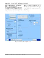
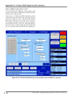
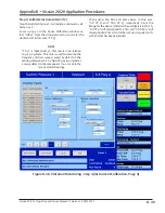
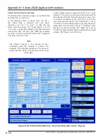
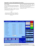
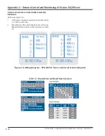
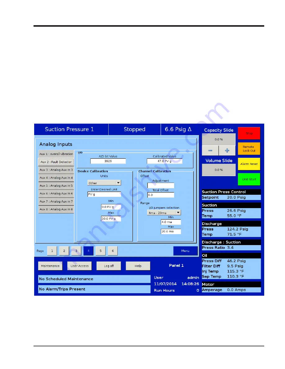
Figure B-38. Vibration Monitoring - Step 4 (Instrument Calibration, Page 4)
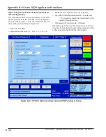
Step 4: Calibrate Instruments (2 of 2)
Now that calibrating Aux 1 is complete, continue to cali-
brate Aux 2.
To set up Aux 2, in the Device Calibration window, se-
lect “Other” from the drop-down menu and enter the
desired unit, in this case, “PV g”.
NOTE
“PV g” is “PeakVue® g”. This unit is in no relation
to g as in g-force. This unit is used to describe the
frequency of stress waves caused by defects in the
moving component. So a high PV g value, indicates
a major defect in the component (i.e. a crack in the
race of a roller bearing).
Then add in the Min and Max values, in this case,
“0.0 PV g” and “50.0 PV g”, respectively. Since the
Range for the device (Vibration Transmitter) is 4-20 mA,
“0.0 PV g” will correspond to 4 mA and “50.0 PV g” will
correspond to 20 mA. No further set up is required, oth-
er than what has been explained.
Summary of Contents for Vilter Vission 20/20
Page 1: ...Vission 20 20TM Micro controller Operation and service manual Version 2 7 ...
Page 2: ......
Page 4: ......
Page 220: ...B 2 Blank Vission 20 20 Operation and Service Manual Emerson 35391SC 2 7 ...
Page 300: ...D 2 Blank Vission 20 20 Operation and Service Manual Emerson 35391SC 2 6 ...
Page 336: ......
Page 337: ......


