3 – 10
Section 3
•
Hardware Architecture
Vission 20/20 • Operation and Service Manual • Emerson • 35391SC 2.7
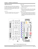
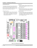
Digital Input Boards
The digital input board converts 120V DC signals from
external devices to signals for the Vission 20/20 pro-
gram. All the signals are digital in that the only two
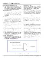
states available are either on or off. See board layout,
Figure 3-6.
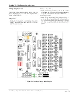
Signal LEDs:
• Marked in the diagram below in light Blue. These
LEDs indicate when a 120VAC input is detected.
Voltage LEDs:
• Marked in the diagram below in Orange. These LEDs
indicate the correct voltage of both the 5V DC and
24V DC power sources.
Communication LEDs:
• Marked in the diagram below in Green. These LEDs
show the active communications between the digital
output board and the Vission 20/20 CPU board.
Address Dipswitches:
• Marked in the diagram below in Red. These dip-
switches are used to assign each board its address
position. The addresses are binary and therefore the
address of a digital input board can only be addressed
as 3 (0011).
Figure 3-6. Digital Input Board Layout
Summary of Contents for Vilter Vission 20/20
Page 1: ...Vission 20 20TM Micro controller Operation and service manual Version 2 7 ...
Page 2: ......
Page 4: ......
Page 220: ...B 2 Blank Vission 20 20 Operation and Service Manual Emerson 35391SC 2 7 ...
Page 300: ...D 2 Blank Vission 20 20 Operation and Service Manual Emerson 35391SC 2 6 ...
Page 336: ......
Page 337: ......

