TOC - 1
Vission 20/20 • Operation and Service Manual • Emerson • 35391SC 2.7
Table of Contents
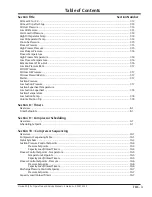
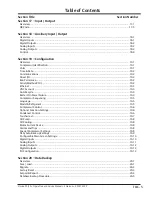
Section Title
Section Number
Important Message................................................................................................................................i
How To Use This Manual .........................................................................................................................TOC-12
Section 1 • Operational Flow Charts
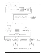
Requirements to Start Compressor ........................................................................................................1-1
Critical Compressor Run Logic at Compressor Start ................................................................................1-1
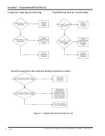
Compressor Amperage Load Limiting ....................................................................................................1-2
High Discharge Pressure Load Limiting ..................................................................................................1-2
Suction Pressure Override Load Limit During Temperature Control ........................................................1-2
Section 2 • Installation Recommendations
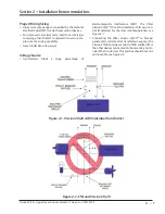
Proper Wiring Sizing ..............................................................................................................................2-1
Voltage Source ......................................................................................................................................2-1
Grounding .............................................................................................................................................2-2
Mixing Voltages .....................................................................................................................................2-2
DC signals ..............................................................................................................................................2-2
Wiring Methods .....................................................................................................................................2-3
Best Practices .........................................................................................................................................2-4
Section 3 • Hardware Architecture
Overview ...............................................................................................................................................3-1
Digital Input/Output (I/O) ......................................................................................................................3-1
Analog Inputs ........................................................................................................................................3-6
Analog Outputs .....................................................................................................................................3-7
Digital & Analog I/O Boards Layout .........................................................................................................3-8
Digital Output Boards ............................................................................................................................3-9
Digital Input Boards ...............................................................................................................................3-10
Digital In-Out Boards .............................................................................................................................3-11
Analog Input Boards ..............................................................................................................................3-12
Analog Input Jumper Tables ...................................................................................................................3-13
Analog Output Boards ...........................................................................................................................3-15
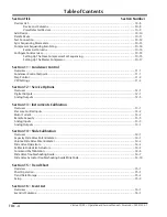
Section 4 • Main Screen
Overview ...............................................................................................................................................4-1
Top Status Bar ........................................................................................................................................4-2
Parameter Bar ........................................................................................................................................4-3
Bottom Status Bar ..................................................................................................................................4-5
Splash Screen .........................................................................................................................................4-6
Step VI Screen ........................................................................................................................................4-7
SOI Solenoid Screen ...............................................................................................................................4-8
Configurable Main Screen ......................................................................................................................4-9
Section 5 • Menu Screen
Overview ...............................................................................................................................................5-1
Navigation Buttons ................................................................................................................................5-1
Section 6 • Compressor Control
Overview ...............................................................................................................................................6-1
Suction Pressure Control, Process Temperature Control, Process Pressure Control
and Discharge Pressure Control .............................................................................................................6-1
Auto-Cycle .............................................................................................................................................6-2
Summary of Contents for Vilter Vission 20/20
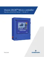
Page 1: ...Vission 20 20TM Micro controller Operation and service manual Version 2 7 ...
Page 2: ......
Page 4: ......
Page 220: ...B 2 Blank Vission 20 20 Operation and Service Manual Emerson 35391SC 2 7 ...
Page 300: ...D 2 Blank Vission 20 20 Operation and Service Manual Emerson 35391SC 2 6 ...
Page 336: ......
Page 337: ......

