6 – 17
Section 6
•
Compressor Control
Vission 20/20 • Operation and Service Manual • Emerson • 35391SC 2.7
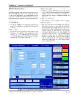
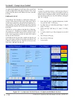
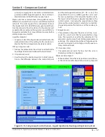
Figure 6-16. Compressor Control Screen - Liquid Injection & Dual Liquid Injection Control
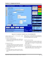
value. By averaging the more stable oil manifold tem-
perature and discharge temperature, the control vari-
able stabilizes and the PID is more easily tuned.
Please note that as stated above, PID algorithms can be
difficult to tune and there is no one set of PID values that
will work. The work required for a compressor to meet
the requirement of its installation vary greatly and there-
fore the amount of heat transferred to the oil varies just
as greatly. We recommend the operator consult PID tun-
ing guides available from many different sources before
attempting to tune this PID.
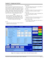
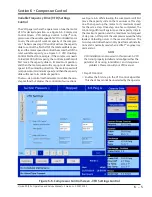
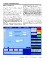
Liquid Inj. Setpoint:
• Setpoint at which the liquid solenoid will activate if in
solenoid control or if the setting for the control vari-
able for the PID is in liquid motorized valve control.
Oil Sep. Temp. Override:
•
Defines the temperature the oil must reach before the
liquid injection solenoid is allowed to be activated.
P = Proportional (Gain):
• Used to adjust the positioning valve in direct propor-
tion to the difference between the control setpoint
and the discharge temperature (SP - DT = error). The
proportional term is a unitless quantity and is used
for coarse adjustment. This setpoint should be set to
the lowest value that gives adequate response to the
control system. Increasing the proportional setting
increases the control system’s sensitivity to small dis-
charge temperature fluctuations and the tendency to
hunt.
I = Integral (reset):
• This parameter integrates the error over time, to ac-
count for a small error that has persisted for a long
time. This quantity is used for fine adjustment. This
setpoint is used to smooth out discharge temperature
variations. This setpoint should be set high enough to
prevent hunting but not too high or it will cause con-
trol system overshoot.
D = Derivative (rate):
• This parameter accounts for how fast the error is
changing, positively or negatively.
Minimum Valve Open %:
• When enabled, this is the valve position used whenev-
er the control variable drops below Liquid inj. Setpoint
Summary of Contents for Vilter Vission 20/20
Page 1: ...Vission 20 20TM Micro controller Operation and service manual Version 2 7 ...
Page 2: ......
Page 4: ......
Page 220: ...B 2 Blank Vission 20 20 Operation and Service Manual Emerson 35391SC 2 7 ...
Page 300: ...D 2 Blank Vission 20 20 Operation and Service Manual Emerson 35391SC 2 6 ...
Page 336: ......
Page 337: ......

