3 – 9
Section 3 • Installation
VSS/VSR/VSM/VSH/VSSH Compressor • Installation, Operation and Service Manual • Emerson • 35391S
Piping
Refer to the ANSI/ASME B31.5 Code for Refrigeration
Piping. The necessary connections to be made to the
screw compressor will vary depending on the type of oil
cooling method used. Main line refrigerant suction and
discharge connections are always necessary.
• Before installing piping, the compressor inlet and
outlet ports should be inspected to ensure no dirt is
present.
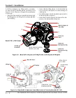
• Piping should be supported so that no piping loads
are transmitted to the compressor casings.
• All piping should be inspected for cleanliness before
installation. As each pipe is connected to the com-
pressor, the coupling alignment should be checked
to ensure that no alteration has taken place.
• If alignment has altered, the compressor is being
strained and the piping supports must be adjusted.
•
It is not sufficient merely to re-align the drive cou
-
pling, as this will not correct the cause of the strain.
• Care must be taken to avoid trapping the lines except
for specific purposes. When traps are used, the hori
-
zontal dimensions should be as short as possible to
avoid excessive oil trapping.
• Lines for ammonia systems must be of steel pipe
with specially designed ammonia service fittings.
Common pipe fittings must NEVER be used as they
will not provide the same service. Steel pipe is gener-
ally used in large installations when joints are welded.
In making up joints for steel pipe, the following proce-
dures should be followed:
• For threaded connections, all threads on the pipe and
fitting should be carefully cleaned to remove all trac
-
es of grease or oil. Threads should then be wiped dry
with a lintless cloth. Only thread filling compounds
suitable for service should be used for making steel
pipe joints. These compounds should be used spar-
ingly, and on the pipe only. Do not put any on the first
two threads to prevent any of the thread sealing com-
pound from entering the piping system. Acetylene or
arc welding is frequently used in making steel pipe
joints, however, only a skilled welder should attempt
this kind of work. Take care to see no foreign materi-
als are left in the pipes and remove all burrs formed
when cutting pipe.
• It is important to avoid short, rigid pipe lines that do
not allow any degree of flexibility. This must be done
to prevent vibration being transmitted through the
pipe lines to the buildings. One method of provid-
ing the needed flexibility to absorb the vibration is to
provide long lines that are broken by 90° Ells in three
directions.
•
A second method would be to install flexible pipe
couplings as close to the compressor unit as possible
with connections run in two different directions, 90°
apart. These flexible connections should be installed
on both the high and low side lines of the compressor
unit.
• Hangers and supports for coils and pipe lines should
receive careful attention. During prolonged opera-
tion of the coils, they may become coated with ice
and frost, adding extra weight to the coil The hangers
must have ample strength and be securely anchored
to withstand the vibration from the compressor and
adequately support the pipe lines.
• For CO
2
piping, the pipes can have smaller diameters
and they will require a greater thickness to withstand
the higher pressures.
•
Smaller Halocarbon and Hydroflourocarbon installa
-
tions use copper pipes with solder type fittings where
possible. The use of screw type fittings in Halocarbon
systems should be held to an absolute minimum, as
these refrigerants, due to their physical properties,
will leak through screw type joints.
• When drawn copper tubing is used for Halocar bon
lines, type “K” or “L” conforming to ASTM B88 should
be used. Soft annealed copper tub ing conforming to
ASTM B280 can also be used for tube sizes not larger
than 1-3/8” in outside diameter. These requirements
are in accordance with the mechanical code for re-
frigeration ANSI B9.1-1971. The type of copper tub-
ing to be used for a given pressure is dependent on
the strength of the copper at the design tempera-
ture. Some local codes forbid the use of Type “L”.
Therefore, before installation, be sure to check local
require ments. Never use type “M” as it does not have
adequate wall thickness to withstand the operat ing
pressures.
•
For halocarbon piping, only wrought copper fittings
should be used. Cast fittings as used for water service
are porous and will allow the refrigerant to escape.
Note this exception: In larger pipe sizes, wrought
fittings are not available. However, specially tested
cast fittings are available and these may be used with
complete safety.
• When soldering copper tubing joints, only silver sol-
der should be used for Refrigerant-22 service. Soft
solder such as “50-50” should never be used, as its
melting point is too low, lacks mechanical strength,
and tends to break down chemically in the presence
of moisture.
• Water supply and drain connections, and equip-
ment using water, should be installed so all the water
may be drained from the system after the plant has
been shut down in cold weather. These precautions

