


3 – 13
Section 3 • Installation
VSS/VSM/VSH/VSSH • Installation, Operation and Maintenance Manual • Emerson • 35391SD
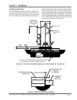
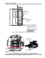
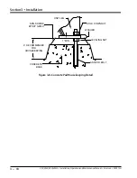
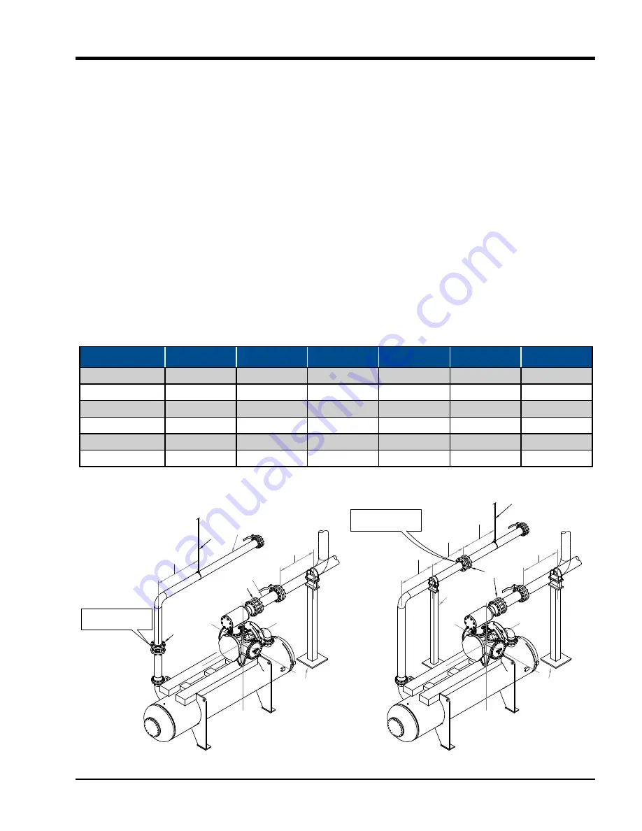
Figure 3-10. Maximum Allowable Flange Loads
DISCHARGE
LINE
5 PIPE
DIAMETERS
CUSTOMER
SUPPORT
3-4 PIPE
DIAMETERS
SUCTION
LINE
X
Z
Z
Y
X
Y
CUSTOMER
SUPPORT
DISCHARGE
LINE
5-6 PIPE
DIAMETERS
CUSTOMER
SUPPORT
3-4 PIPE
DIAMETERS
SUCTION
LINE
X
Z
Z
Y
X
Y
HANGER
CHECK
VALVE
HANGER
CHECK
VALVE
CUSTOMER SUPPORTS
WHEN CHECK VALVE
IS MOUNTED HERE
CUSTOMER SUPPORTS
WHEN CHECK VALVE
IS MOUNTED HERE
5 PIPE
DIAMETERS
5 PIPE
DIAMETERS
CHECK
VALVE
Nozzle Dia. (in.)
Fz (lbf)
Fy (lbf)
Fx (ft-lbf)
Mzz (ft-lbf)
Myy (ft-lbf)
Mxx (ft-lbf)
4
400
400
400
300
300
300
6
600
600
600
500
500
500
8
900
900
900
1000
1000
1000
10
1200
1200
1200
1200
1200
1200
12
1500
1500
1500
1500
1500
1500
14
2000
2000
2000
2000
2000
2000
Table 3-1. Maximum Allowable Flange Loads
may be drained from the system after the plant has
been shut down in cold weather. These precautions
will avoid costly damage to the equipment due to
freezing.
This information is taken from ASHRAE 15-89 and ANSI/
ASME B31.5. The installing contractor should be thor
-
oughly familiar with these codes, as well as any local
codes.
CAUTION
Accumulated liquid in the suction header can damage
the compressor if not drained. Always drain headers
(suction and discharge headers) prior to start-ups.
Failure to comply may result in damage to equipment.
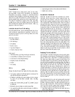
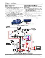
Flange Loads
The ideal load applied to flanges of the compressor unit
is zero. However, it’s not practical to expect that no loads
will be applied to unit connections. Thermal, dead, live,
wind & seismic loads must be considered and even toler
-
ated. Well supported external piping connected to the
compressor will still result in some loads applying forces
and moments in three axes to unit flanges.
The most important issue is the motor-compressor mis
-
alignment caused by external forces (F in lbf) and mo
-
ments (M in ft-lbf) imposed by plant piping. In Figure
3-10 and Table 3-1, are the maximum allowable forces
and moments that can be applied to compressor flanges
when the compressor is mounted on an oil separator.
It must be noted that it is necessary to check for com
-
pressor shaft movement when the job is complete. In
no case shall the attached piping be allowed to cause
Summary of Contents for Vilter VSH
Page 2: ......
Page 30: ...2 4 Blank VSS VSM VSH VSSH Installation Operation and Maintenance Manual Emerson 35391SD ...
Page 54: ...3 24 Blank VSS VSM VSH VSSH Installation Operation and Maintenance Manual Emerson 35391SD ...
Page 74: ...4 20 Blank VSS VSM VSH VSSH Installation Operation and Maintenance Manual Emerson 35391SD ...
Page 144: ...5 70 Blank VSS VSM VSH VSSH Installation Operation and Maintenance Manual Emerson 35391SD ...
Page 156: ...7 4 Blank VSS VSM VSH VSSH Installation Operation and Maintenance Manual Emerson 35391SD ...
Page 158: ...8 2 Blank VSS VSM VSH VSSH Installation Operation and Maintenance Manual Emerson 35391SD ...
Page 204: ...8 48 Blank VSS VSM VSH VSSH Installation Operation and Maintenance Manual Emerson 35391SD ...
Page 206: ...A 2 Blank VSS VSM VSH VSSH Installation Operation and Maintenance Manual Emerson 35391SD ...
Page 210: ...B 4 Blank VSS VSM VSH VSSH Installation Operation and Maintenance Manual Emerson 35391SD ...
Page 216: ...C 6 Blank VSS VSM VSH VSSH Installation Operation and Maintenance Manual Emerson 35391SD ...
Page 219: ......
Page 221: ......
Page 224: ......
Page 225: ......
Page 226: ......
Page 242: ...E 12 Blank VSS VSM VSH VSSH Installation Operation and Maintenance Manual Emerson 35391SD ...
Page 248: ...G 2 Blank VSS VSM VSH VSSH Installation Operation and Maintenance Manual Emerson 35391SD ...
Page 249: ......


