


5 – 15
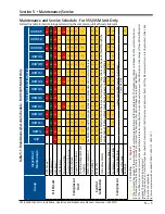
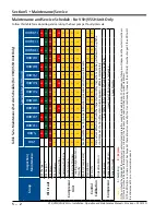
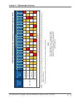
Section 5 • Maintenance/Service
VSS/VSM/VSH/VSSH • Installation, Operation and Maintenance Manual • Emerson • 35391SD
Oil Pump Strainer Screen Installation
20. Install screen in strainer body.
21. Install four bolts to secure strainer cover on strainer
body.
22. Tighten bolts, see Appendix A.
23. Close drain valve on oil pump strainer.
24. Install plug on drain valve.
Oil Filter Element Installation
(For 3111A Oil Filter Housing - See Figure 5-9)
25. Lubricate new O-ring with clean system oil.
26.
Install O-ring on inside of filter head.
27.
Install new filter element on internal port of head
assembly. Make sure filter element is fully seated.
28. Lubricate threads of locking ring with clean system
oil.
29. Hand tighten locking ring only. Install locking ring
and filter housing on head assembly until filter
housing bottoms. Do not overtighten locking ring.
30. Using dry nitrogen gas, pressurize isolated oil line
through bleed valve of filter housing. Check for
leaks on replaced components.
31. Evacuate isolated oil line to 29.88” Hg (1000 mi-
crons) and close bleed valve.
32.
Install plug on bleed valve of filter housing.
33.
Slowly open oil supply valve and allow oil to fill oil
line.
34.
Open filter outlet valve.
35.
Check oil level and fill oil separator to non-operat
-
ing level, see Oil Charging procedure.
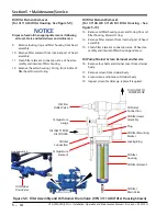
Oil Filter Element Installation
(For 3110A OR 3112A Oil Filter Housing - See
Figure 5-10)
36.
Install new filter element on internal port of head
assembly. Make sure filter element is fully seated.
37. Lubricate new O-ring with clean system oil.
38.
Hand tighten oil filter housing cover only. Install
O-ring and oil filter housing cover on oil filter
housing.
39. Using dry nitrogen gas, pressurize isolated oil line
through bleed valve of filter housing. Check for
leaks on replaced components.
40. Evacuate isolated oil line to 29.88” Hg (1000 mi-
crons) and close bleed valve.
41.
Install plug on bleed valve of filter housing.
42.
Slowly open oil supply valve and allow oil to fill oil
line.
43.
Open filter outlet valve.
44.
Check oil level and fill oil separator to non-operat
-
ing level, see Oil Charging procedure.
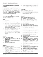
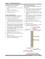
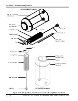
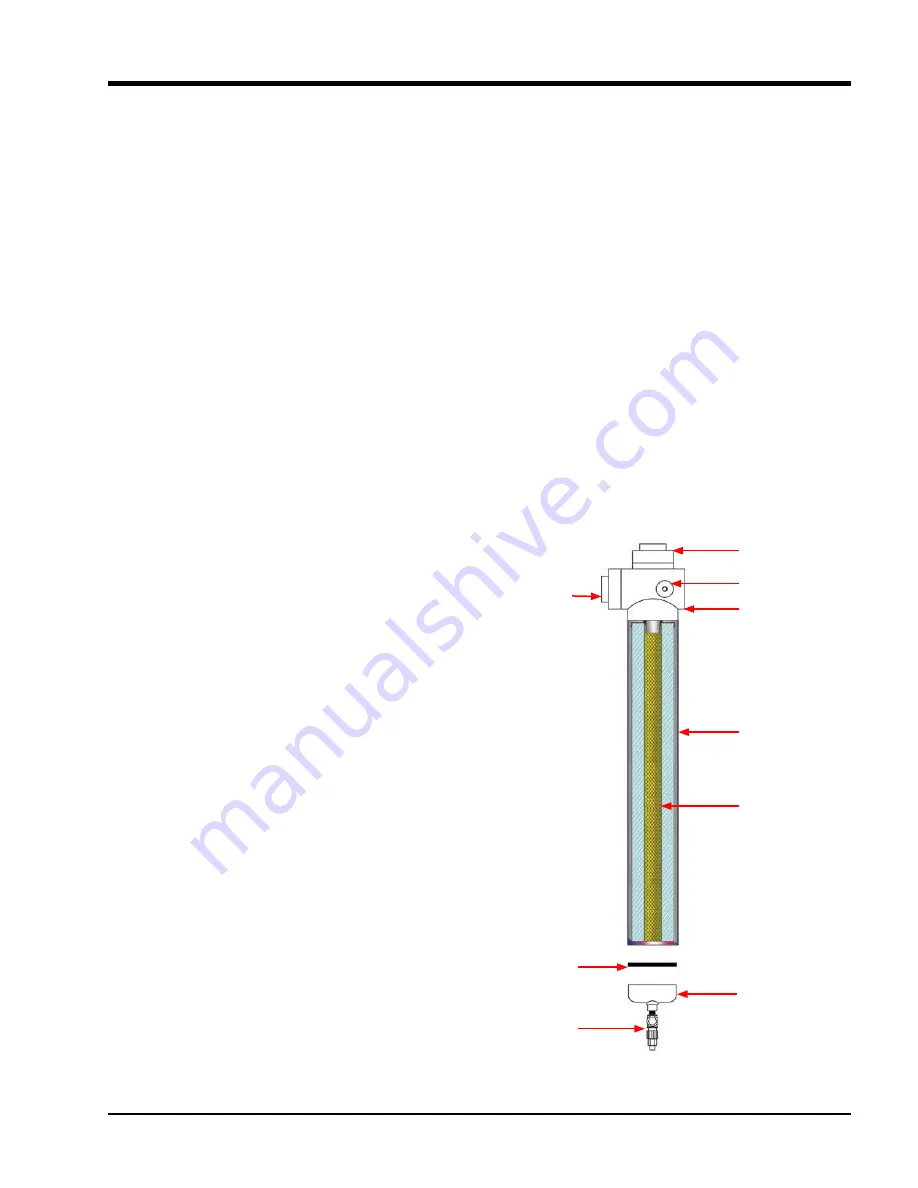
Oil Filter Head
Assembly
Oil Filter
Element
Oil Outlet
Connection
Oil Filter
Housing
O-ring
Oil Filter
Housing Cover
Oil Filter Drain
Valve with Plug
Oil Inlet
Connection
Plug
Figure 5-10. Filter Assembly
(VPN 3112A Oil Filter Housing Shown)
Summary of Contents for Vilter VSH
Page 2: ......
Page 30: ...2 4 Blank VSS VSM VSH VSSH Installation Operation and Maintenance Manual Emerson 35391SD ...
Page 54: ...3 24 Blank VSS VSM VSH VSSH Installation Operation and Maintenance Manual Emerson 35391SD ...
Page 74: ...4 20 Blank VSS VSM VSH VSSH Installation Operation and Maintenance Manual Emerson 35391SD ...
Page 144: ...5 70 Blank VSS VSM VSH VSSH Installation Operation and Maintenance Manual Emerson 35391SD ...
Page 156: ...7 4 Blank VSS VSM VSH VSSH Installation Operation and Maintenance Manual Emerson 35391SD ...
Page 158: ...8 2 Blank VSS VSM VSH VSSH Installation Operation and Maintenance Manual Emerson 35391SD ...
Page 204: ...8 48 Blank VSS VSM VSH VSSH Installation Operation and Maintenance Manual Emerson 35391SD ...
Page 206: ...A 2 Blank VSS VSM VSH VSSH Installation Operation and Maintenance Manual Emerson 35391SD ...
Page 210: ...B 4 Blank VSS VSM VSH VSSH Installation Operation and Maintenance Manual Emerson 35391SD ...
Page 216: ...C 6 Blank VSS VSM VSH VSSH Installation Operation and Maintenance Manual Emerson 35391SD ...
Page 219: ......
Page 221: ......
Page 224: ......
Page 225: ......
Page 226: ......
Page 242: ...E 12 Blank VSS VSM VSH VSSH Installation Operation and Maintenance Manual Emerson 35391SD ...
Page 248: ...G 2 Blank VSS VSM VSH VSSH Installation Operation and Maintenance Manual Emerson 35391SD ...
Page 249: ......


