


15
Description
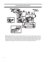
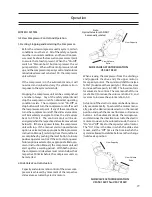
DESCRIPTION OF GAS SYSTEM FOR A STANDARD
COMPRESSOR SET
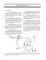
The gas passes through a stop valve and a check
valve and then through a mesh strainer mounted
directly to the inlet flange. The check valve is nec-
essary to prevent reverse rotation and potential
damage or oil loss at shut down. The suction gas
enters the compressor housing through the top inlet
flange, at the driven end of the unit.
After compression the gas is discharged from the
discharge manifold directly into a oil separator tank.
On the discharge of the oil separator tank another
check valve is positioned to prevent the entry of
gas or liquid refrigerant in to the separator when
the compressor is shut down. The separator should
be allowed to equalize slowly to suction pressure
through a small bypass line around the suction check
or combination stop/check valve. This will allow the
compressor to start without a pressure differential
across it, reducing the starting power requirements.
From the discharge manifold, the gas/oil exits the
compressor housing and passes into the oil sepa-
rator through a pipe elbow. The separator vessel
serves to separate the oil from the gas as the gas
stream moves from one end of the separator to
the other. The majority of the oil is separated from
the gas in the primary chamber of the vessel due to
changes in direction and velocity reduction. Any re-
maining oil mist is separated from the gas stream as
the stream passes through the coalescing elements
and into the secondary chamber of the vessel. The
gas at discharge pressure then exits at the far end
of the separator.
Oil collected in the bottom of the separator is
drained off to be recirculated in the oil injection
system. The injection oil temperature is controlled
by several means the first of which is a three-way
mixing valve, which mixes hot oil directly from the
separator with oil which has passed through the
oil cooler to obtain oil at the desired temperature.
This oil then passes through a filter to remove any
contaminants, which may have been picked up
from the process gas, and is injected back into the
compressor.
DESCRIPTION OF OIL SYSTEM FOR A STANDARD
COMPRESSOR SET
At start oil at is drawn from the oil separator tank by the
oil pump, and passes through a oil cooler and micronic
filters to the oil supply inlet on the compressor frame.
From there it internally lubricates all points internal to
the compressor. After start-up when the compressor
develops sufficient differential pressure the oil pump
can be shut down and the oiling can take place without
the use of the oil pump. On units with low pressure dif-
ferentials such as booster and low pressure differential
high stage compressors, the oil pump must remain on
whenever the unit is running to maintain sufficient oil
flow.
Summary of Contents for VSG
Page 2: ...2 ...
Page 4: ...4 ...
Page 56: ...56 ...
Page 58: ...58 Gate Rotor ...
Page 64: ...64 Main Rotor ...
Page 66: ...66 Slide Valve Cross Shafts and End Plate ...
Page 68: ...68 Capacity Slide Volume Slide Carriage Assembly Slide Valve Carriage Assembly ...
Page 72: ...72 Actuator Command Shaft ...
Page 74: ...74 VSG Screw Compressor Miscellaneous Frame Components ...
Page 78: ...78 Replacement Tools 291 1551 ...
Page 82: ...82 Gaterotor Assembly ...
Page 86: ...86 Main Rotor Slide Valve Cross Shafts End Plate Models VSG301 401 Counter Clockwise ONLY ...
Page 88: ...88 Main Rotor Slide Valve Cross Shafts End Plate Models VSG501 701 Clockwise ONLY ...
Page 92: ...92 Actuator Command Shaft ...
Page 94: ...94 Model VSG 501 701 Model VSG 301 401 Miscellaneous Frame Components ...
Page 96: ...96 Housing Accessories Miscellaneous Frame Components ...
Page 99: ...99 ...


