TEST
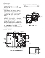
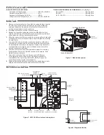
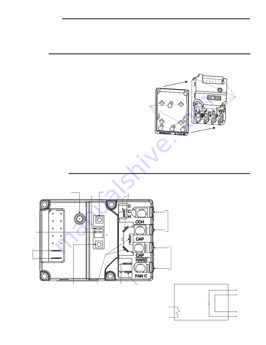
Tri-Color LED
Fault/Status Indicator
Count Button
Hardstart
Option
Fan
Common
Compressor/Fan
Capacitor Outputs
Short Cycle
Protection
Delay
Dipswitch
Brownout
Protection
Brown
Dipswitch
C
Y
Thermostat
Input
Test
Button
Crankcase Heater
Power
Line
Inputs
L
1
L
2
Run
Common
Delay
Brown
ON
COUNT
Compressor
Outputs
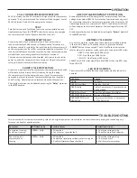
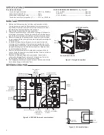
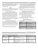
MOUNTING
QUICK REFERENCE
1.
Disconnect power to the condensing unit or heat pump at the
disconnect switch and/or main electrical panel. Ensure that all
sources of power are disconnected before proceeding.
2.
Label wires and remove old contactor.
3.
Find a suitable mounting location inside the control box. Rotate
SureSwitch as necessary to allow space for wiring and other
components.
4.
Loosen four housing captive screws attaching the bottom
mounting plate to the main housing and separate the mounting
plate from the main housing.
5.
The bottom of the mounting plate has four mounting holes that
match the typical mounting screw locations of a single or two-pole
contactor. Secure the bottom mounting plate to the control box
using the two self-tapping screws provided.
6.
Replace the main housing on the mounting plate and secure by
tightening all four housing captive screws. Take care to avoid over
tightening.
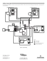
7.
Connect line and control voltage wiring. Refer to the wiring
diagrams provided for more information. Tighten the
L
1
,
L
2
,
R
and
C
lugs to the recommended torque specifications.
8.
Affix the provided Quick Reference Label inside the control box for
future service.
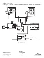
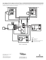
CONTROL
CIRCUIT
L
2
L
1
Run
Common
LOAD
LINE
C
Y
Figure
1
- Two Piece Design
Figure
3
- Electrical Diagram
MAIN HOUSING
Housing
Screws
Mounting
Holes
MOUNTING PLATE
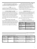
SPECIFICATIONS
ELECTRICAL RATINGS
Line Voltage Input
...........................................
240 VAC, 50/60 Hz
Full Load Amperes (FLA)
.................................
40 A
Locked Rotor Amperes (LRA)
..........................
200A
Control (Coil) Voltage (Y, C)
.............................
24 VAC, 50/60 Hz
RECOMMENDED TERMINAL TORQUE – L
1
, L
2
, R and C
#4
– 6 AWG .....................................................
45
in-lbs
#8
AWG ..........................................................
40
in-lbs
#10
–
14
AWG .................................................
35
in-lbs
Figure
2
-
49
P
11
-
843
Terminals and Switches


