1592019030 XEV02D GB r1.2 04.06.2015
XEV02D
3/4
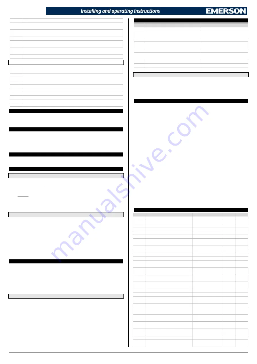
dCt
Cooling time for DG compressor after DLT alarm:
0 to 255 min
dLn
Number of DLT alarms in dLi hours before blocking compressor:
0 to 15,
0=function disabled.
dLi
Time interval (in hours) in which to check dLn number of DLT alarms:
0 to 24
hours; 0=function disabled.
CEd
Maximum compressor capacity (in percentage) in case of probe error:
0 to 100%
Cdd
Maximum compressor capacity (in percentage) in case of DLT alarm and for time
dLd:
0 to 100%
CEi
Maximum compressor capacity (in percentage) in case of regulation input error:
0 to 100%
dEr
Alarm delay in case of regulation input/probes reading error:
0 to 999 sec
OTHER
A2F
ALARM key timed function configuration (push button timed, 3 sec): nu
=not used;
onF=ON-OFF function.
Adr
Serial address:
1 to 247
bAU
Baudrate for serial communication:
9.6
=9600 baud;
19.2
=19200 buad.
dP1
Analogue output value (read only)
dP2
Probe P2 value (read only)
d1S
Digital input status display (isolated contact) (read only)
d2S
Digital input status display (not isolated contact) (read only)
rEL
Release Firmware (read only)
Ptb
Parameters table code (read only)
Pr2
Protected parameters menu access
8. DIGITAL INPUTS
The device is provided with two digital inputs. One is free of voltage and the other is at high voltage
and both can be configured as cooling call. In this way the cooling signal can come from instruments
with direct load outputs or via instruments with output without voltage.
9. ELECTRICAL CONNECTIONS
The instrument is provided with pluggable screw terminal block to connect cables with a cross section
up to 2.5 mm
2
. Heat-resistant cables have to be used. Before connecting cables make sure the power
supply complies with the instrument’s requirements. Separate the probe cables from the power supply
cables, from the outputs and the power connections. Do not exceed the maximum current allowed on
each relay, in case of heavier loads use a suitable external relay.
10. RS485 SERIAL LINE
All models can be connected to a MODBUS network by using the 2-wire RS485 port. The XWEB
related library and the MODBUS protocol can be issued on customer request from DIXELL.
11. USE THE HOT-KEY
11.1
PROGRAM A HOT-KEY FROM THE INSTRUMENT (UPLOAD)
1)
Program one controller with the front keypad.
2)
When the controller is ON, insert the
HOT-KEY
and push
UP
button; the “
uPL
”
message
appears followed a by flashing “
End
”
.
3)
Push
SET
button and the “
End
” will stop flashing.
4)
Turn OFF the instrument, remove the
HOT-KEY
and
then turn it ON again.
NOTE
: the “
Err
” message is displayed in case of any failed programming operation. In this case, push
again
UP
button if you want to restart the upload again or remove the
HOT-KEY
to abort the
operation.
11.2
PROGRAM AN INSTRUMENT USING A HOT KEY (DOWNLOAD)
1)
Turn OFF the instrument.
2)
Insert a pre-programmed
HOT-KEY
into the 5-PIN connector and then turn the Controller ON.
3)
Automatically the parameter list present into the
HOT-KEY
will be downloaded into the
Controller memory. The “
doL
” message will blink during this operation, followed a by a flashing
“
End
” label.
4)
After 10 seconds the instrument will restart working with the new parameters.
5)
Remove the
HOT-KEY
.
NOTE:
the “
Err
” message is displayed in case of any failed programming operation. In this case, push
again
UP
button if you want to restart the upload again or remove the
HOT-KEY
to abort the
operation.
12. ALARM MENU
Press the
ALARM
button to access the alarms database menu if. This menu contains a
LIFO
format
log of the last 10 registered alarms. The menu structure is as follows:
-
the alarm number in AL0...AL9 format (0 is the oldest alarm, 9 is the last received alarm) is
displayed once accessed;
-
it is possible to scroll the registered alarms by using the
UP
and
DOWN
buttons;
-
it is possible to display the following alarm information (in sequence) by using the
SET
button:
the alarm code (3 digit label according to that described) and alarm duration in
h.mm
(1 minutes
resolution, max stored value is 19h59min).
12.1
ALARMS ARCHIVE ERASING:
All saved alarms can be deleted by keeping the
ALARM+SET
key pressed for 5 sec when into
ALARM MENU. The display will show the “rSt” label (flashing) for 3 sec and then the default display
visualization will be restored (
Lod
variable).
NOTE:
-
All saved alarms can be also deleted via special MODBUS command.
13. DISPLAY MESSAGES
Mess.
Cause
Outputs
A02
Digital input configured as
EAL
function is active Unchanged
A03
Missing regulating signal (analogue input drops
below
dSL
value)
Unchanged
E01
DLT alarm active
Output disabled, alarm output activated
E02
A
dLn
number of DLT alarms in time interval (in
hours)
dLi
was detected.
Output disabled, alarm output activated
E03
Digital input configured as
bAL
function is active Output disabled, alarm output activated
E05
Missing regulating signal (analogue input drops
below
dSL
value more than
dEr
time)
Output disabled, alarm output activated
E07
Low temperature alarm active
Output disabled, alarm output activated
P1
Analogue input error
Output disabled, alarm output activated
P2
Temperature transducer in error
Output disabled, alarm output activated
13.1
ALARM RECOVERY
Probe alarms “
P1
” and “
P2
” start
dEr
seconds after the fault in the read value; they automatically stop
few seconds after the probe restarts normal operation. Check connections before replacing the probe.
Alarms
E01, E03
and
E05
automatically stop as soon as their root causes disappear.
Alarm
E02
and
E07
require a manual re-start by switchinf OFF and ON the device or by sending a
MODBUS command.
14. TECHNICAL DATA
Housing:
self extinguishing ABS
Case:
4 DIN modules 70x135mm with male and female connectors; depth 60mm
Mounting:
DIN RAIL mounted in an omega (3) din rail
Protection:
IP20
Connections:
screw terminal block
2.5 mm
2
wiring
Power supply:
24Vac/dc ±10%; 110VAC ±10% or 230VAC ±10%
Power absorption: depending on connected valve
20VA max
Display:
3.5 digits with icons, red LEDs, height 14.2 mm
Temperature input:
1 temperature probe
PT1000 probe:
-55 to 200°C (-67 to 392°F)
NTC10k probe:
-40 to 110°C (-40 to 230°F)
NTC86k probe:
-40 to 180°C (-40 to 356°F)
Analogue control input:
0 to 10Vdc
4 to 20mA
Digital inputs:
1
free of voltage
1 isolated (voltage depending on the power supply)
Digital outputs:
1 relay output, 8(3)A, 250VAC
1 open collector output, max current 40mA
TRIAC output:
max 30W
Data storage:
on the non-volatile memory (EEPROM)
Kind of action:
1B
Pollution degree:
normal
Software Class:
A
Operating temperature:
0 to 55°C (32 to 131°F)
Storage temperature:
-25 to 60°C (-13 to 140°F)
Relative humidity:
20 to 85% (no condensing)
Resolution:
0.1°C or 1°F
Precision a 25°C (77°F):
±0.7°C ±1digit
15. STANDARD VALUES
Label
Description
Range
Default
Level
oA1
Digital output 1 configuration
nu; ALr; CPR; dmd
CPr
Pr1
oA2
Digital output 2 (o.c.) configuration
nu, ALr
nu
Pr2
oP1
Digital output 1 polarity
oP; CL
oP
Pr1
oP2
Digital output 2 (o.c.) polarity
oP; CL
oP
Pr2
tbA
Alarm output deactivation
no; Yes
no
Pr2
bEn
Buzzer (software) management
on; oFF
on
Pr2
P2C
Temperature probe configuration (it
depends on the hardware)
nu; Pt1; ntC; n86
(*)
Pr1
o2
Probe P2 calibration
-12 to 12°C; -21 to 21°F
0.0
Pr1
PA4
Analogue input at 4mA or 0V
0 to 100%
0.0
Pr2
P20
Analogue input at 20mA or 10V
0 to 100%
100
Pr2
Lod
Default displayed variable
PEr; Ain; P2
PEr
Pr1
CF
Units
of
measurement
for
temperature
°C; °F
°C
Pr1
rES
Temperature resolution (valid only if
CF=°C)
in; dE
dE
Pr1
i1F
Digital input 1 configuration (voltage
free contact)
nP; EAL; bAL; onF
EAL
Pr1
i2F
Digital input 2 configuration (high
voltage input)
nP; EAL; bAL; onF
onF
Pr1
i1P
Digital input 1 polarity
oP; CL
CL
Pr1
i2P
Digital input 2 polarity
oP; CL
CL
Pr1
Sut
Start up time: valve activation time
before starting the regulation
0.0 to 25.5 sec
3.0
Pr1
tdG
Modulation time interval
6 to 40 sec
20
Pr1
ALL
Low temperature alarm
-30 to 200°C;
-22 to 392°F
-30
Pr2
dLL
Low temperature alarm activation
delay
0 to 999 sec
180
Pr2
dLt
Discharge line temperature
-30 to 200°C;
-22 to 392°F
145
Pr1
dth
Differential
0 to 99.9°C;
0 to 999°F
10
Pr1
dLd
DLT alarm activation delay
0 to 999 sec
60
Pr1
dCt
Cooling time for DG compressor
after DLT alarm
0 to 255 min
10
Pr1


