2
YARWAY
SERIES 460D3 AND 515D3 INTEGRAL STRAINER HIGH PRESSURE DISC TRAPS
INSTRUCTION, OPERATION AND MAINTENANCE MANUAL
INSTALLATION
Piping
to and from the trap should be equal to
trap size or one size larger. Discharge line for
short runs equal to trap size; larger for long
runs. Avoid configurations that would cause
excessive back pressure.
Blow the System Out
before installing the
trap. Frequent strainer blowdown or cleaning
is recommended on a new system. Conditions
will dictate frequency of blowdown in
normal operation.
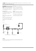
Valves-
Use globe type (Yarway Welbond
®
)
for isolation strainer blow-down, or for test
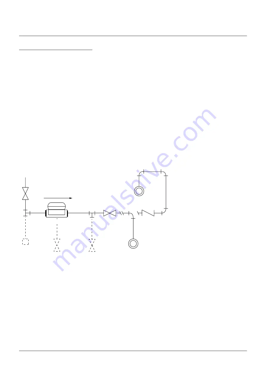
(see Figure 1).
Bypasses not recommended except for critical
installations. If discharge is to a multi-station
or overhead return, put a swing check valve
in discharge line to prevent backflooding on
shutdown. Select a check valve suitable for the
application.
FIGURE 1
Equipment drain
Yarway Welbond shut off valve
Dirt leg
(optional)
Steam trap
Strainer blow-down (optional)
½ Yarway Welbond globe valve
Test valve (optional)
Yarway Welbond globe valve
Elevated return
Check valve
Return main
WARNING
Hot discharge from this product may cause severe burns. Discharge must be piped away or directed so
that persons in the vicinity are not endangered. This product must be isolated, vented and cool to the
touch before repairing or inspecting.
Locate Trap
below outlet from equipment
(gravity flow). If trap must be above the drain
provide a 'U' or lift fitting at the bottom of the
riser before the trap (water seal). The trap may
be installed in a horizontal or vertical line or at
any angle so long as the discharge is downward
or horizontal.
Welding-
Socket welding of this trap body to
the piping should be completed according to
applicable codes, standards, and procedures.
DO NOT make electrical welding connections
to the trap body or any other part of the trap
to prevent internal arcing. Electrical ground
should be made to the pipe and not the trap.


