background image

20

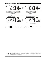
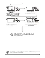
 4.2 Changing and Saving Set Value

SET

°C

SV

P

When SET button is pressed, SV LED 

lights on and SET value is shown on 

the displays.

SET

°C

SV

P

SET Value Screen

Change the SET value with 

increment and decrement 

buttons.

SET

°C

SV

P

Press SET button for saving the 

SET value

SV LED lights off and main operation 

screen is shown.

SET

°C

SV

P

Main Operation Screen

SET Value Screen

i

If no operation is performed in Set value mode for 20 seconds, device turns to main 
operation screen automatically.

SET value is can be adjusted from minimum set value parameter           to maximum set value          
parameter            , Which can be accessed from programming parameters.

Main Operation Screen

Summary of Contents for ESM-3710

Page 1: ...ing or cooling function Selection of operation with hysteresis Adjustable temperature offset Set value low limit and set value high limit boundaries Relay or SSR driver output Operation selection of c...

Page 2: ...explained Operation Also in these sections there are warnings to prevent serious injury while doing the physical and electrical mounting or using the device Explanation of the symbols which are used i...

Page 3: ...N 3 5 3 PT 100 AND PT 1000 CONNECTION 3 6 GALVANIC ISOLATION TEST VALUES OF ESM 3710 TEMPERATURE CONTROLLER 3 7 OUTPUT CONNECTIONS 3 7 1 RELAY OUTPUT CONNECTION 3 7 2 SSR DRIVER OUTPUT CONNECTION 4 FR...

Page 4: ...e Low Voltage Directive 2004 108 EC The Electromagnetic Compatibility Directive has been designed and manufactured to the following specifications EN 61000 6 4 2007 EMC Generic Emission Standard for I...

Page 5: ...controlling temperature They can be used in many applications with their On Off control form heating and cooling control form and easy use properties Some application fields which they are used are be...

Page 6: ...ice Use a cloth dampened in ethyl alcohol or water to clean the external plastic case A BC D E FG HI U V W Z 0 00 2 0 0 1 Relay Output resistive load 10 A 250 V V 1 NO 1NC Output 1 E Supply Voltage A...

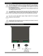
Page 7: ...eep the power off until all of the wiring is completed so that electric shock and trouble with the unit can be prevented Never attempt to disassemble modify or repair this unit Tampering with the unit...

Page 8: ...t View and Dimensions of ESM 3710 Temperature Controller 77 mm 3 03 inch 35 mm 1 38 inch Temperature Controller ESM 3710 SET C SV P Mounting Clamp Front Panel IP65 protection NEMA 4X Panel surface max...

Page 9: ...2 3 Panel Cut Out 29 mm 1 14 inch 71 mm 2 79 inch Maximum 15 mm 0 59 inch 58 5 mm 2 30 inch 4 mm 0 16 inch 9 110 mm 4 33 inch min 50 mm 1 97 inch min...

Page 10: ...ude Up to 2000 m Operating Conditions Forbidden Conditions Corrosive atmosphere Explosive atmosphere Home applications The unit is only for industrial applications 2 4 Environmental Ratings 2 5 Panel...

Page 11: ...es that located left and right sides of the device and make the unit completely immobile within the panel 2 6 Installation Fixing Clamp 2 1 1 2 11 2 7 Removing from the Panel c c Before starting to re...

Page 12: ...e installer to ensure that the configuration is correct Device parameters has factory default values These parameters must be set according to the system s needs Only qualified personnel and technicia...

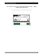
Page 13: ...led and personnel injury c Temperature Sensor Input TC NTC PTC PT 100 or PT 1000 Relay or SSR Driver Output Supply Voltage Input It must be determined in order 230 V V 15 50 60 Hz 1 5 VA 115 V V 15 50...

Page 14: ...5 05 0 1 00 00 2 0 0 0 Y ca L N OUTPUT 230 VV 15 50 60Hz 1 5VA 3 4 1 5 NO NC C 10A 250V V 6 7 8 9 10 11 12 CAT II J Type TC 0 to 800 C Scale Device Label for J Type 0 800 scaled Thermocouple input 230...

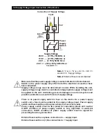
Page 15: ...lling the unit supply voltage range must be controlled and appropriate supply voltage must be applied to the unit Controlling prevents damages in unit and system and possible accidents as a result of...

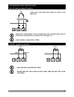
Page 16: ...0M W i i 12 11 10 Pay attention the cable colours of PTC probe while doing the PTC probe connection i i WHITE RED 16 Connect the wires with the polarity as shown in the figure left Always use compensa...

Page 17: ...4 5 Ground 12 2000V V 2000V V 2000V V 2000V V 2000V V For ESM 3710 5 500V V For ESM 3710 3 Input resistance is greater than 10M W i i 12 11 10 3 5 3 PT 100 and PT 1000 Connection PT 1000 12 11 10 PT 1...

Page 18: ...Element SSR 2 Device L N 1 Fuses must be selected according to the application c c Max 15 V Z Max 28mA Fuses must be selected according to the application c Device 1 Load L N 2 Max 10A V T Fuse NC C...

Page 19: ...sly increment and decrement number become 100 4 Front Panel Definition and Accessing to the Menus Temperature Controller ESM 3710 SET C SV P Led indication of Output is active If blinks Compressor pro...

Page 20: ...Press SET button for saving the SET value SV LED lights off and main operation screen is shown SET C SV P Main Operation Screen SET Value Screen i If no operation is performed in Set value mode for 2...
Page 21: ...19 9 C 99 9 C Switch On Delay After Power On Parameter Default 0 When power is first applied to the device this time delay must be expired for activation of the compressor It can be adjusted from 0 to...

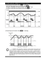
Page 22: ...Time HSt HSt Time 2 If Operating Type Parameter Value 0 Heating i 22 In ON OFF control algorithm temperature value is tried to keep equal to set value by opening or closing the last control element O...

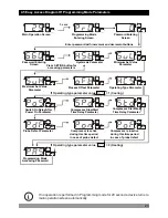
Page 23: ...eriod in case of probe defect Compressor is inactive during this time period in case of probe defect SET C SV P 5 secs Password Entering Screen Main Operation Screen SET C SV P SET C SV P Programming...
Page 24: ...e Entering Screen Press increment button for accessing to the password Password Entering Password Entering Enter programming mode accessing password with increment and decrement Press SET OK button fo...

Page 25: ...ming mode for 20 seconds device turns to main operation screen automatically Change the parameter with increment and decrement SET C SV P SET C SV P i Other Programming mode parameters can be accessed...

Page 26: ...age Category II Pollution Degree II office or workplace none conductive pollution Operating Conditions Continuous Supply Voltage and Power 230 V V 15 50 60 Hz 1 5 VA 115 V V 15 50 60 Hz 1 5 VA 24 V V...

Page 27: ...Phone 90 224 261 1900 Fax 90 224 261 1912 Repair and Maintenance Service Information Emko Elektronik Sanayi ve Ticaret A Demirta Organize Sanayi B lgesi Karanfil Sk No 6 16369 BURSA TURKEY Phone 90 22...

Reviews: