background image

29

4.2.4 Power supply

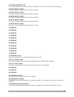
Sensing Options Generator Frq En/Dis

All Warnings Are Latched En/Dis

ENABLE: Speed sensing will be derived from the generator output frequency.
DISABLE: Speed sensing not will be derived from the generator output frequency.

ENABLE: Warnings and pre-alarms will latched when triggered. To reset the alarm either an external
reset must be applied to one of the inputs or the 'Reset' pushbutton operated, once the triggering
condition has cleared.
DISABLE: Normal operation, the warnings and pre-alarms (except spare inputs, because they have
their latching or non-latching selections) will automatically reset once the triggering condition has
cleared.

Note:

dis = disable

Min

Default Unit

GENERATOR GENERAL (

)

Generator->General

Max

Sensing Options Generator Frq En/Dis

Sens.option gen.freq

ENABL

ENABL/DISBL

All Warnings Are Latched En/Dis

All warning are latch

ENABL/DISBL

DISBL

Min

Default

Max

Working Calendar Disable or Enable

Working Calendar Work Start Time on Monday

Working Calendar Work Stop Time on Monday

Working Calendar Work Start Time on Tuesday

Working Calendar Work Stop Time on Tuesday

Working Calendar Work Start Time on Wednesday

Working Calendar Work Start Time on Thursday

Working Calendar Work Start Time on Friday

Working Calendar Work Start Time on Saturday

Working Calendar Work Start Time on Sunday

Disable/enable select
Start time on monday
Stop time on monday
Start time on tues.
Stop time on tuesday
Start time on wednes.

Start time on thurs.

Start time on friday

Start time on satur.

Start time on sunday

Unit

Stop time on wednes.

Stop time on thursday

Stop time on friday

Stop time on saturday

Stop time on sunday

Working Calendar Work Stop Time on Wednesday

Working Calendar Work Stop Time on Thursday

Working Calendar Work Stop Time on Friday

Working Calendar Work Stop Time on Saturday

Working Calendar Work Stop Time on Sunday

GEN

(

)

WORKING CALENDAR

Generator->Working calendar

23.59

23.59

23.59

23.59

23.59

23.59

23.59

23.59

23.59

23.59

23.59

23.59

23.59

23.59

H.Min

H.Min

H.Min

H.Min

H.Min

H.Min

H.Min

H.Min

H.Min

H.Min

H.Min

H.Min

H.Min

H.Min

0.00

0.00

0.00

0.00

0.00

0.00

0.00

0.00

0.00

0.00

0.00

0.00

0.00

0.00

0.00

0.00

0.00

0.00

0.00

0.00

0.00

23.59

23.59

23.59

23.59

23.59

23.59

23.59

DISBL ENABL

/

DISBL

Min

Default

POWER SUPPLY BATTERY (Power Supply

)

->Battery

Max

Battery Undervolts Warning
Battery Undervolts Warning Reset

Battery Undervolts Volts Delay

Battery Overvolts Warning

10.0

Battery Overvolts Warning Reset

6.0(dis) 30.0

10.5

6.0

1.0

0.0

9.9

30.0
29.5

30.0

30.0

6.0 30.0

Battery Overvolts Delay

1.0

0.0

9.9

6.0(dis)

Under volt
Under volt reset
Under volt delay
Over volt
Over volt reset
Over volt delay

Unit

V

Z

V

Z

V

Z

V

Z

Sec

Sec

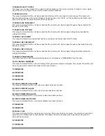
The parameters in this page are used for the battery voltage low and high alarms.

Summary of Contents for TRANS MINI ATS

Page 1: ...TS AUTOMATIC TRANSFER SWITCH User Manual EMKO ELEKTRON K A Demirta Org San Bolg Karanfil Sk No 6 TR 16369 Bursa TURKEY Ý Þ þ Phone Faks Url E mail 90 224 261 1900 90 224 261 1912 exposales emkoelektronik com tr www emkoelektronik com tr emko emkoelektronik com tr ...

Page 2: ... 4 2 2 Mains 4 2 3 Generator 4 2 4 Power Supply 4 2 5 Engine 4 2 6 Inputs 4 2 7 Outputs 4 2 8 Timers 4 2 9 User Adjustment 2 1 Unit Configuration 2 2 Panel Mounting Figure 2 1 Front View 2 3 Electrical Connection 3 Definition Of Front Panel And Accessing To The Parameters 4 Parameters 5 Specifications 6 Other Informations CONTENTS Page 4 Page 7 Page 6 Page 5 Page 7 Page 5 Page 5 Page 5 Page 14 Pag...

Page 3: ...ms to the following directives 2006 95 EC The Low Voltage Directive 2004 108 EC The Electromagnetic Compatibility Directive has been designed and manufactured to the following specifications EN 61000 6 4 2007 EMC Generic Emission Standard for Industrial Environments EN 61000 6 2 2005 EMC Generic Immunity Standard for Industrial Environments EN 61010 1 2001 Safety Requirements for electrical equipm...

Page 4: ... display 1 1 General Specifications 1 2 Warranty EMKO Elektronik warrants that the equipment delivered is free from defects in material and workmanship This warranty is provided for a period of two years The warranty period starts from the delivery date This warranty is in force if duty and responsibilities which are determined in warranty document and instruction manual performs by the customer c...

Page 5: ...nstallation of this product please read the instruction manual and warnings below carefully 2 Installation Ýçindekiler 2 1 Unit Configuration Ýçindekiler 2 2 Panel Mounting The unit is designed for panel mounting Fixing is by two screw fixings Insert the unit in the panel cut out from the front Insert the fixings in the slotted at the corners of the unit and tighten the fixing screws to secure the...

Page 6: ...r Configurable Input 3 Mains Break Feedback or Configurable Input 2 Emergency Stop or Configurable Input 1 27 26 25 8A 8A 30 2 24 29 1 L1 GENERATOR Max 300VV MAINS L2 L3 N M G L1 L2 L3 N Electrical interlock Mechanical interlock 4 3 Max 300VV Mains Contactor Relay Generator Contactor Relay FUSE 1 FUSE 2 FUSE 3 FUSE 4 2 FUSE FUSE FUSE FUSE 4 FUSE 5 8A T FUSE 6 FUSE 7 8A T 1 2 3 2A T 28 31 Configura...

Page 7: ...ped 7 The STARTbutton is used for starting the engine when the unit is in the Manual Mode In Programming mode it operates as an Up button changing cursor position or Increment button increase parameter value 7 4 This button is used for showing next page in normal operation In Programming mode it is used for entering parameter edit section saving parameter value and showing next parameters on the c...

Page 8: ...ssages Current page name 128x64 Dot matrix LCD display Use the button to select which Data display page screen is to be displayed Next When enter button pressed for 2 seconds menu options displayed 8 MAINS V12 380V V1 V Mains okay 220 V23 380V V2 220V V31 380V V3 220V ü AUTO RESET ...

Page 9: ...nerator voltage L1 L2 Generator frequency Generator active energy Generator reactive energy Load Page1 I1 PF1 Load Current L1 Load power factor L1 Load Page2 P Q S Load active power Load reactive power Load apparent power Power Supply Page Battery volt Battery supply voltage 9 Data display pages on the LCD display MAINS V12 380V V1 V Mains okay 220 V23 380V V2 220V V31 380V V3 220V MAINS Fq 50 0Hz...

Page 10: ...ated digit is displayed as 1 else it is displayed as 0 Conf in 1 Conf in 2 Conf in 3 Conf in 4 Conf In 5 Not available Not available Not available Output status information If an output is active related digit is displayed as 1 else it is displayed as 0 Conf out 1 Conf out 2 Conf out 3 Conf out 4 Conf out 5 Conf out 6 Generator contactor Mains contactor Date Time Page Date Time Day Month Year Hour...

Page 11: ...9 time Generator voltage L1 N Load Current L1 Event Log Page2 1 2 Fq kW Mains The second page of related event log Generator frequency Generator total active power This message indicates that Load is supplied by mains 11 EVENT LOG 1 1 04 06 2013 17 28 09 Emergency stop V1 220V I1 26A V2 220V EVENT LOG 1 2 Fq 50 0Hz kW 510 Mains V3 220V Event Log display pages on the LCD display ...

Page 12: ...2 380V On load Fq 50 0Hz kWh 30600 kVArh 7200 LOAD On load I1 20A PF1 0 84 POWER SUPPLY Battery volt 12 0Vdc On load LOAD P 170kW Q 40kVAr S 210kVA On load INPUT OUTPUT 1 4 5 8 Inputs 000X XXXX Outputs 0000 0010 On load DATE TIME 05 06 2013 16 51 16 Example 1 Displaying all pages Data display 12 ü ü ü ü ü ü ü ...

Page 13: ...TO RESET LCD display language selection English Display MAINS V12 380V V1 V Mains okay 220 V23 380V V2 220V V31 380V V3 220V English Display V12 380V V1 V 220 V23 380V V2 220V V31 380V V3 220V Chinese Display Ö µçÔ MAINS V12 380V V1 V Mains okay 220 V23 380V V2 220V V31 380V V3 220V ü AUTO RESET Program Language Event log AUTO RESET ü Program Language Event log AUTO RESET ü Press Enter button for ...

Page 14: ...level Power level GEN POWER LEVEL Under power shutdown Under power prealarm Under power reset Over power shutdown GEN POWER LEVEL Over prealarm Over power power reset Shutdown delay time Reverse power set GEN POWER LEVEL Under power shutdown 150 kVA GEN POWER LEVEL Over power prealarm 280 kVA GEN POWER LEVEL Over prealarm Over power power reset Shutdown delay time Reverse power set GEN POWER LEVEL...

Page 15: ... default sets Reset factory sets DEFAULT SETTINGS Save setting to def no SYSTEM Date time set Default settings Password TECHNICIAN SETTING System Mains Generator Power supply MAINS Volt level Frequency level Actions MAINS VOLT LEVEL Over volt trip Over volt reset Under volt trip Under volt reset MAINS VOLT LEVEL Under volt trip 320 Vac MAINS Volt level Frequency level Actions MAINS FREQ LEVEL Unde...

Page 16: ...es GEN WORKING CALENDAR Disable enable select DISBL GEN WORKING CALENDAR Stop time on tuesday Start time on wednes Stop time on wednes Start time on thurs GEN WORKING CALENDAR Stop time on thursday Start time on friday Stop time on friday Start time on satur GEN WORKING CALENDAR Stop time on saturday Start time on sunday Stop time on Sunday GEN WORKING CALENDAR Disable enable select Start time on ...

Page 17: ... delay 5 SEC TECHNICIAN SETTING Engine Inputs Outputs Timers START TIMERS Mains transient delay Mains fail start dely Remote start delay Generator fail delay START TIMERS Safety on delay Warming up time Horn duration TIMERS Start timers Stopping timers STOPPING TIMERS Mains return delay Remote stop delay Cooling time Fail to stop delay STOPPING TIMERS Mains return delay 5 SEC STOPPING TIMERS Mains...

Page 18: ... offset Current offset Battery offset Mains voltage offset Gen BATTERY OFFSET Batt volt offset ü ü ü CURRENT OFFSET Current I1 offset CURRENT OFFSET Current I1 offset 0 A USER ADJUSTMENT voltage offset Current offset Battery offset Mains voltage offset Gen CURRENT OFFSET Current I1 offset AUTO ü ü ü ...

Page 19: ... the Stop Reset button is pressed any time previous page can be accessed MAINS V12 380V V1 V Mains okay 220 V23 380V V2 220V V31 380V V3 220V To exit from programming mode any time press Stop Reset for 2 seconds button MAINS V12 380V V1 V Mains okay 220 V23 380V V2 220V V31 380V V3 220V ü AUTO RESET Press Enter button for 2 seconds to access the menu options When the Enter button is pressed the pa...

Page 20: ...realarm Over volt reset Unit Shutdown delay time Generator Voltage Shutdown Delay Time GENERATOR VOLT LEVEL Generator level Volt 0 0 10 0 1 0 Sec 75 0 30 0 dis 75 0 75 0 Hz 30 0 dis Min Default Max Generator Under Frequency Pre Alarm Generator Under Frequency Pre Alarm Reset Generator Over Frequency Shutdown Generator Over Frequency Pre Alarm Generator Over Frequency Pre Alarm Reset 45 0 46 0 58 0...

Page 21: ...s every started at 08 30 o clock if it is enabled 17 30 The working function is every stopped at 17 30 o clock if it is enabled 08 30 The working function is every started at 08 30 o clock if it is enabled 17 30 The working function is every stopped at 17 30 o clock if it is enabled 08 30 The working function is every started at 08 30 o clock if it is enabled 17 30 The working function is every st...

Page 22: ... Gen brk cls contact Gen brk cls relay Gen brk cls time Gen brk open relay Gen brk open time Type of Breaker Mains brk cls relay Mains brk cls time Mains brk open relay Mains brk open time Break close puls time Mains brk cls contact Transfer time Spring loading time Retry number Break open pulse time Sec Sec 1 250 0 5 0 5 Sec Sec Sec Sec Sec 3 5 1 250 1 250 Hardware Breaker Selection 0 Mains and G...

Page 23: ...AINS CLOSE TIMER if mains closed input selected MAIN OPEN BREAKER RELAY TYPE MAINS OPEN TIMER if mains closed input selected BREAKER CLOSE PULSE TIME if Gen Close Breaker Relay Type or Main Close Breaker Relay Type parameter is selected as 1 BREAKER OPEN PULSE TIME if Gen Open Breaker Relay Type or Main Open Breaker Relay Type parameter is selected as 1 TRANSFER TIME SPRING LOADING TIME RETRY NUMB...

Page 24: ... configured as Generator Closed Auxiliary a become in active the module will issue a generator failed to open alarm This is used to monitor the closure of the mains contactor or breaker It will only operate if an auxiliary input is configured as Mains Closed Auxiliary and connected to the auxiliary on the mains contactor or breake hould the Mains Closed Auxiliary input become active the timer the ...

Page 25: ...B breaker and after that the unit want to give close command the same breaker this time for between open and close commands because if there is no delay between open and close commands can be problem the motorized switches GCB or MCB breaker number of this parameter If each try there is no close feedback after last try the alarm will be activated Min Default Unit LCD DISPLAY System LCD display Max...

Page 26: ...Default Unit DEFAULT SETTINGS System Default settings Max Save setting to default Reset default sets Save setting to def Reset default sets YES NO NO Reset factory sets Reset factory sets YES NO NO YES NO NO Save setting to default Reset default sets Reset factory sets If this parameter is selected as Yes the unit s currently parameters save as default sets After this parameter is reset automatica...

Page 27: ... Delay Time Hz Hz Hz Hz 30 0 30 0 dis 30 0 75 0 75 0 Under freq prealarm Under freq reset Over freq shutdown Over freq prealarm Over freq reset Shutdown delay time Unit GENERATOR LEVEL FREQ Generator level Frequency 75 0 43 0 Hz Under freq shutdown Generator Under Frequency Shutdown 30 0 dis 0 0 10 0 1 0 Sec 4 2 3 Generator Mains Failure Detection En Dis Look Mains Failure at Stop Mode En Dis Alwa...

Page 28: ...arm And Shutdown 0 1 2 3 Generator Over Current Actions Disable Warning Alarm Only No Shutdown Electrical Trip Alarm Off Load Generator Followed By Shutdown After Cooling Shutdown Alarm And Shutdown 0 1 2 3 9999 9999 9999 9999 9999 9999 kVA kVA kVA kVA 0 dis 0 dis 0 0 dis 0 dis 0 Min Default Max Generator Under Shutdown Power Generator Under Pre Alarm Power Generator Under Pre Alarm Reset Power Ge...

Page 29: ...aturday Working Calendar Work Start Time on Sunday Disable enable select Start time on monday Stop time on monday Start time on tues Stop time on tuesday Start time on wednes Start time on thurs Start time on friday Start time on satur Start time on sunday Unit Stop time on wednes Stop time on thursday Stop time on friday Stop time on saturday Stop time on sunday Working Calendar Work Stop Time on...

Page 30: ... is started at 12 20 o clock 1 Monday 2 3 4 5 6 7 Period Day of week Start time Min Default EXERCISE Engine Exercise Max 0 dis 99 dis 1 7 0 0 23 59 0 00 1 Time of period Week Start time Generator exercise working period on related day Generator exercise working day of week Generator exercise work start time on related day Unit Min H Min 4 2 5 Engine Min Default Unit ENGINE GENERAL Engine General M...

Page 31: ...ty On 2 Always Active If Select From List 0 Remote Start On Load 1 Remote Start Off Load 2 Auxiliary Mains Fail 3 Reserved 4 Reserved 5 Reserved 6 Simulate Auto Button 7 Simulate Test Button 8 Reserved 9 Simulate Start Button 10 Simulate Stop Button 11 Generator Closed Auxiliary 12 Generator Load Inhibit 13 Mains Closed Auxiliary 14 Mains Load Inhibit 15 Auto Restore Inhibit 16 Auto Start Inhibit ...

Page 32: ...larity Indication Activation Select from list 0 250 0 Sec 1 Active delay Input active delay If Select From List 0 Remote Start On Load 1 Remote Start Off Load 2 Auxiliary Mains Fail 3 Reserved 4 Reserved 5 Reserved 6 Simulate Auto Button 7 Simulate Test Button 8 Reserved 9 Simulate Start Button 10 Simulate Stop Button 11 Generator Closed Auxiliary 12 Generator Load Inhibit 13 Mains Closed Auxiliar...

Page 33: ...t On Load 1 Remote Start Off Load 2 Auxiliary Mains Fail 3 Reserved 4 Reserved 5 Reserved 6 Simulate Auto Button 7 Simulate Test Button 8 Reserved 9 Simulate Start Button 10 Simulate Stop Button 11 Generator Closed Auxiliary 12 Generator Load Inhibit 13 Mains Closed Auxiliary 14 Mains Load Inhibit 15 Auto Restore Inhibit 16 Auto Start Inhibit 17 Panel Lock 18 Scheduled Runs Exercise Inhibited 19 R...

Page 34: ...t On Load 1 Remote Start Off Load 2 Auxiliary Mains Fail 3 Reserved 4 Reserved 5 Reserved 6 Simulate Auto Button 7 Simulate Test Button 8 Reserved 9 Simulate Start Button 10 Simulate Stop Button 11 Generator Closed Auxiliary 12 Generator Load Inhibit 13 Mains Closed Auxiliary 14 Mains Load Inhibit 15 Auto Restore Inhibit 16 Auto Start Inhibit 17 Panel Lock 18 Scheduled Runs Exercise Inhibited 19 R...

Page 35: ...t On Load 1 Remote Start Off Load 2 Auxiliary Mains Fail 3 Reserved 4 Reserved 5 Reserved 6 Simulate Auto Button 7 Simulate Test Button 8 Reserved 9 Simulate Start Button 10 Simulate Stop Button 11 Generator Closed Auxiliary 12 Generator Load Inhibit 13 Mains Closed Auxiliary 14 Mains Load Inhibit 15 Auto Restore Inhibit 16 Auto Start Inhibit 17 Panel Lock 18 Scheduled Runs Exercise Inhibited 19 R...

Page 36: ... of the Stop button and is used to provide a remotely located Stop push button This input is used to provide feedback to allow the unit to give true indication of the contactor or circuit breaker switching status It should be connected to the generator load switching device auxiliary contact On Load If this input is active operation will be similar to the Remote Start On Load function except that ...

Page 37: ...wn This input is used to prevent the generator for starting in the event of a programmed scheduled exercise run occurring While the input is active no scheduled runs will occur If the input is active when a schedule run is called for and is removed during the running period the gen set will start and complete any remaining scheduled running time If one of the configurable inputs are selected as En...

Page 38: ...OR LOW FREQUENCY PRE ALARM 56 GENERATOR LOW FREQUENCY SHUTDOWN 57 GENERATOR LOW VOLTAGE PRE ALARM 58 GENERATOR LOW VOLTAGE SHUTDOWN 59 GENERATOR STOPPING 60 GENERATOR OPEN BREAKER 61 HORN OUTPUT LATCHED 62 HORN OUTPUT PULSED 63 LAMP TEST 64 RESERVED 65 RESERVED 66 RESERVED 67 RESERVED 68 MAINS CLOSED AUXILIARY 69 MAINS FAILED TO CLOSE 70 MAINS FAILED TO OPEN 71 MAINS FAILURE 72 MAINS HIGH FREQUENC...

Page 39: ...TPUT 2 Outputs Conf output 2 CONF OUTPUT 3 Outputs Conf output 3 CONF OUTPUT 4 Outputs Conf output 4 CONF OUTPUT 5 Outputs Conf output 5 CONF OUTPUT 6 Outputs Conf output 6 Polarity Polarity Polarity Polarity Polarity Function Function Function Function Function 0 Normally Open Close To Activate 1 Normally Close Open To Activate 0 Normally Open Close To Activate 1 Normally Close Open To Activate 0...

Page 40: ...utput indicates that a shutdown alarm has been activated This output can only be reset by removal of the fault and by then pressing the RESET button or by using an external alarm reset input 0 NOT USED 3 AUDIBLE ALARM 4 AUTO START INHIBIT 5 AUXILIARY MAINS FAILURE 6 BATTERY HIGH VOLTAGE 7 BATTERY LOW VOLTAGE 8 CALLING FOR SCHEDULED RUN EXERCISE 11 RESERVED 12 COMMON ALARM 13 COMMON ELECTRICAL TRIP...

Page 41: ...s output indicates that digital input 4 alarm has occurred This output indicates that digital input 5 alarm has occurred This output indicates that an emergency stop alarm has occurred This output indicates that the engine has not started after the specified number of attempts This output indicates that the generator has failed to stop within the selected time The output indicates that the generat...

Page 42: ...wn has occurred This output indicates that a generator high voltage warning pre alarm has occurred This output indicates that a generator high voltage shutdown has occurred This output indicates that a digital input has been configured as generator load inhibit is active This output indicates that a generator low frequency warning pre alarm has occurred This output indicates that a generator low f...

Page 43: ...ing AC mains supply voltage has exceeded the voltage limit setting This output indicates that a digital input has been configured as mains load inhibit is active This output indicates that the unit has sensed that the incoming AC mains supply frequency has fallen below the frequency setting This output indicates that the unit has sensed that the incoming AC mains supply voltage has fallen below th...

Page 44: ...l external logic circuitry Starting alarms are armed as soon as the unit commences starting of the engine and remain armed until the engine at rest The output indicates that the unit is in the Auto mode The output indicates that the unit is in the Manual mode The output indicates that the unit is in the Stop mode The output indicates that the unit is in the Test mode This output indicates that the...

Page 45: ...116 117 118 119 120 122 REMOTE CONTROL ACTIVE 121 This output indicates that the engine is being controled remotely RESERVED RESERVED RESERVED RESERVED RESERVED RESERVED 45 ...

Page 46: ...delays loading the generator until it has stabilised Once this timer is expired the Close generator signal will be given and the generator is available to be loaded unit This timer dictates how long the will wait after it has received a remote start signal before it will attempt to start This prevent un necessary starting on a fluctuating mains supply etc This timer dictates how long the will igno...

Page 47: ...d back to mains This is the time the generator is to run off load once the load transfer signal has ceased This gives the engine time to cool down before shutdown Once the has given a shutdown signal to the engine it expects the engine to come to rest It monitors the Oil pressure and speed sensing sources and if they still indicate engine movement when this timer expires a Fail To Stop alarm signa...

Page 48: ...ffset 2 Mains V Offset 3 20 20 20 VV VV VV Min Default Unit GEN VOLTAGE OFFSET User adjustment Gen voltage offset Max 0 20 Gen V1 offset Generator V1 Offset 20 VV Min Default Unit CURRENT OFFSET User adjustment offset Current Max 0 20 Current I1 offset Current I1 Offset 20 AV Min Default Unit BATTERY OFFSET User adjustment Battery offset Max 0 0 5 Batt volt offset Battery Voltage Offset 5 0 VZ ...

Page 49: ...cy stop error Fail to start alarm Generator breaker not closed alarm Generator breaker not opened alarm Generator over frequency prealarm Generator over frequency shutdown Generator over voltage shutdown Generator over voltage prealarm Generator stop error Generator under frequency prealarm Generator under frequency shutdown Generator under voltage shutdown Generator under voltage prealarm Mains b...

Page 50: ...ower prealarm Battery high error Battery low error Changed mode to auto Changed mode to manual Changed mode to stop Changed mode to test Emergency stop error Fail to start alarm Generator breaker not closed alarm Generator breaker not opened alarm Generator over frequency prealarm Generator over frequency shutdown Generator over voltage prealarm Generator over voltage shutdown Generator stop error...

Page 51: ...tery voltage can be 0 VDC for max 50 ms during cranking battery voltage should be at least nominal voltage before cranking 8 to 32 V accuracy 1 FS resolution 0 1 V 3 Resolution 1 V 5 to 99 9Hz min 20 VAC Ph N Accuracy 0 25 FS Resolution 0 1 Hz 3 Resolution 1 V 5 to 99 9Hz min 20 VAC Ph N Accuracy 0 25 FS Resolution 0 1 Hz 5A RS 232 Generator contactor relay output 8A 250V Mains contactor relay out...

Page 52: ... Phone 90 224 261 1900 Fax 90 224 261 1912 Repair and maintenance service information Emko Elektronik Sanayi ve Ticaret A Þ Demirtaþ Organize Sanayi Bölgesi Karanfil Sk No 6 16369 BURSA TURKEY Phone 90 224 261 1900 Fax 90 224 261 1912 Thank you very much for your preference to use Emko Elektronik Products Your Technology Partner www emkoelektronik com tr ...

Reviews: