background image


Emona SIGEx USER MANUAL      © Emona Instruments  

21 


SIGEx™ SOFTWARE INSTALLATION  

& SFP OPERATION 


Installing NI DAQ and NI ELVIS software 

Before  installing  the  EMONA  SIGEx  software,  ensure  that  the  NI  DAQ  and  NI  ELVIS 
software  has  been  correctly  installed  as  per  the  accompanying  NI  DAQ  and  NI  ELVIS  user 
instructions.  

Use NI MAX (Measurement and Automation Explorer) to determine which Device Number the 
NI ELVIS unit is associated with, if this is not known. 

Confirm the correct operation of NI ELVIS before proceeding. 


Installing the EMONA SIGEx software 


Installation procedure 
Insert the CD-ROM in your PC drive, open the CD-ROM directory and run 

SIGEx-setup.exe 


The CD-ROM supplied with the SIGEx Kit includes the following items: 


SIGEx-Main SFP (Soft Front Panel). 

A large SFP which allows all SIGEx switches and knobs to be controlled on-screen. 
 

The SIGEx CD-ROM also includes a soft copy of the Lab Manual, User Manual, and Instructors 
Manual 
 
Emona SIGEx Lab Manual Volume 1, User Manual, Instructors Manual in PDF format 


SIGEx CD-ROM version and upgrade procedure 

Please  contact  Emona  via  the  web  to  obtain  the  latest  version  SIGEx  CD-ROM: 
 

www.emona-tims.com


SIGEx software is supplied as a “LabVIEW 2009 executable”. 
 
“LabVIEW  2009  executable”  form  requires  either  LV2009  or  later,  or  the  LabVIEW  2009 
runtime engine to be installed on the users machine. For users with LabVIEW versions prior to 
LV2009, this RTE is available for free download from the NI website. 
 
From time to time, EMONA Instruments will release upgraded documentation and accompanying 
software. These will be downloadable, and registered users of SIGEx will be advised by email 
when these upgrades become available. 
 

Summary of Contents for SIGEx ETT-311

Page 1: ...ETT 311 SIGEx User Manual Signal Processing Add on Board for the NI ELVISTM...

Page 2: ......

Page 3: ...ETT 311 SIGEx User Manual Signal Processing Add on Board for the NI ELVISTM...

Page 4: ...any means including any network or Web distribution or broadcast for distance learning or stored in any database or in any network retrieval system without the prior written consent of Emona Instrumen...

Page 5: ...GITAL OUT NI ELVIS Function 6 6 FUNCTION GENERATOR NI ELVIS Function 7 7 INTEGRATE DUMP HOLD 8 8 INTEGRATORS 9 9 LIMITER 10 10 MULTIPLIER 11 11 PCM ENCODER 12 12 PCM DECODER 14 13 RC NETWORK 16 14 REC...

Page 6: ......

Page 7: ...then experiments will not be able to be completed succcessfully SIGEx bringing BLOCK DIAGRAMS to life Using the SIGEx board students bring to life the block diagrams that populate signal processing te...

Page 8: ...e SIGEx board are used and re used in experiments just as blocks of the block diagram reappear in many different implementations SIGEx Integration with NI ELVIS SIGEx uses the NI ELVIS for all electro...

Page 9: ...re made and broken Sockets on the RIGHT HAND SIDE are for signal OUTPUTS All analog outputs are low impedance typically 330 ohms Again this is to reduce effects when connections are made and broken Di...

Page 10: ...he Emona SIGEx teaching philosophy is that students are free to make mistakes while patching together experiments By observing the result of their mistake when the signals do not look as expected they...

Page 11: ...switch is in the OFF position Installing SIGEx on NI ELVIS II When installing the SIGEx add in module in the NI ELVIS II PROTOTYPE PCI SLOT always carefully check the alignment is correct before push...

Page 12: ...II Prototype Board Power is OFF Before removing the SIGEx add in module from the NI ELVIS II PROTOTYPE PCI SLOT always turn the PROTOTYPING BOARD POWER switch OFF ALWAYS STORE THE SIGEx BOARD IN A ES...

Page 13: ...gn the SIGEx circuit board with the NI ELVIS PCI socket and slide into position 5 Operation Power up the SIGEX add in module by switching the NI ELVIS PROTOTYPING BOARD POWER switch to ON Confirm the...

Page 14: ...viii Introduction Conventions Emona Instruments Pty Ltd...

Page 15: ...Refer to section Using the SIGEx SFP for information on setting input gains ADDER block f g has fixed input gains of 1 Care must be taken when adjusting the input gains to avoid overloading the inter...

Page 16: ...Blocks a and b Inputs three inputs a0 a1 a2 and b0 b1 b2 Gain Range 2 to 2 for a0 a1 a2 b0 b1 and b2 Gain Adjust on screen and manual using GAIN ADJUST 0 002 maximum resolution Bandwidth approx 100kH...

Page 17: ...alog outputs DAC0 and DAC1 are provided from the NI ELVIS PCI connector These signals are provided directly from the NI ELVIS unit These two signals are generated through LabVIEW programs such as the...

Page 18: ...nstruments BASEBAND LPF An active 4th order 1 8kHz lowpass filter USE The lowpass filter may be used to filter analog signals greater than 1 8kHz BASIC SPECIFICATIONS Bandwidth DC to approx 1 8kHz Gai...

Page 19: ...tal level CLK signal must be provided for the SAMPLE and HOLD block to function DELAY BLOCKS Three independent analog signal DELAY blocks are provided Each DELAY block is clocked by a common CLK signa...

Page 20: ...the SIGEx SFP to provide PULSE GENERATOR and digital CLOCK output signals as required by the selected experiment The SFP contains the frequency and duty cycle controls DO0 is provided as an additiona...

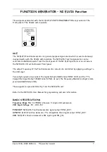
Page 21: ...requency of the Function Generator can also be controlled by applying a voltage to the VCO input Two output signals are provided the Signal Output SIGEx label FUNC OUT and the TTL Compatible Signal Ou...

Page 22: ...s again The I H output changes at each occurrence of a positive edge at the CLK input The IN signal is integrated over the period of the CLK signal At the occurrence of each positive CLK edge the inte...

Page 23: ...pt analog level signals Their common integration rate is set by 2 bit dip switch labeled INTEGRATION RATE The integration rate is set as illustrated in the following table SWITCH INTEGRATIO N RATE A B...

Page 24: ...ifies them before presenting to the output The amplified signals are then limited or clipped as defined by the user The limiter gain is set as illustrated in the following table SWITCH LIMITER GAIN A...

Page 25: ...single independent MULTIPLIER module as pictured above MULTIPLIER modules has DC coupled inputs as per their front panel labels Note that the output of each MULTIPLIER is input X times input Y times a...

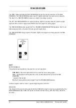
Page 26: ...igital data The PCM ENCODER always requires a digital clock signal USE INPUT SIGNALS Two input signals are required for correct operation the analog signal to be digitized INPUT and the sampling bit c...

Page 27: ...e analog to digital converter by the PCM ENCODER module s internal sample and hold circuit CLK is the applied bit clock at the CLK socket PCM DATA is the serial data signal at the PCM DATA output FS i...

Page 28: ...termine which bit is the start of each byte of digital data The PCM DECODER always requires the same digital clock signal as is being used at the PCM ENCODER USE INPUT SIGNALS Three digital level sign...

Page 29: ...nstruction filtering so that individual steps in the conversion process may be observed if desired NB The output range of the PCM DECODER does not match the input range of the PCM ENCODER Hence the in...

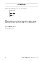
Page 30: ...inal RC network is provided USE A single 10k ohm resistor and 100nF capacitor are provided which can be patched in any RC configuration required They are free wheeling and GND connection must be made...

Page 31: ...SIGEx USER MANUAL Emona Instruments 17 RECTIFIER Precision halfwave rectifier USE Halfwave buffered precision rectifier BASIC SPECIFICATIONS Input analog level signal 2Vpk pk Bandwidth DC to 10kHz ap...

Page 32: ...al data which means that it is easier to observe the data in experiments The SEQUENCE GENERATOR block outputs four different digital sequences switch selectable by the user The SYNC terminal outputs a...

Page 33: ...s 4 switch selectable Sequence Lengths X 31 63 63 and 16 383 bits Sync indicates start of sequence X Line Code output bipolar 2V replica of X Sequence description UP UP Maximal length single bit SYNC...

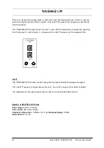
Page 34: ...passed by adjusting the front panel fc control knob fc is known as the cutoff frequency of the lowpass filter USE The TUNEABLE LPF module accepts analog level signals and outputs analog level signals...

Page 35: ...SFP Soft Front Panel A large SFP which allows all SIGEx switches and knobs to be controlled on screen The SIGEx CD ROM also includes a soft copy of the Lab Manual User Manual and Instructors Manual E...

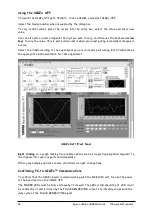
Page 36: ...iment you are currently performing Each TAB contains the appropriate instrumentation for that experiment SIGEx Soft Front Panel Right clicking on a graph display box enables options such as exporting...

Page 37: ...he following 1 That the correct DEV number is selected for the NI DAQ in the SIGEx SFP 2 That the SIGEx SFP is running 3 That the PROTOTYPING BOARD POWER switch is in the ON position 4 That the PC NI...

Page 38: ...BNC coaxial oscilloscope leads Documentation 1 x User Manual 1 x Experiment Manual 1 x Instructor Manual Software SIGEx SFP Manuals in soft format COMMON ELECTRICAL SPECIFICATIONS Input impedance typ...

Page 39: ...tromagnetic Compatibility Directive 2004 108 EC and could lead to prosecution The equipment when operated does not cause electromagnetic disturbance to apparatus situated outside its immediate electro...

Page 40: ......

Page 41: ......
Page 42: ...eriments in Modern Analog and Digital Signal Processing a Systems Emona Instruments Pty Ltd 78 Parramatta Road web www emona tims com Camperdown NSW 2050 telephone 61 2 9519 3933 AUSTRALIA fax 61 2 95...

Reviews: