3
Measuring Electrical Resistance
1. Connect the black measuring tip to the socket labelled as "COM"
and the red conductor to the socket labelled as "V/Ω" (connect
the red measuring tip to "+").
2. Switch to the function marked as Ω. Choose a measuring range
and place the measuring tips where you wish to measure electrical
resistance. The measured values will be displayed.
• If the range is exceeded, the display will show the number "1".
Switch to a higher range.
• If no load is connected to the input or the input circuit is open, the
value of "1" will be displayed for all ranges.
• When checking a circuit with resistance, make sure the circuit is
without power and all capacitors are discharged.
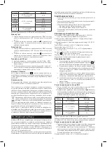
Range
Accuracy
Deviation
200 Ω
±0.8 % of reading
± 3 counts
0.1 Ω
2 kΩ
±0.8 % of reading
± 1 count
1 Ω
20 kΩ
10 Ω
200 kΩ
100 Ω
2 MΩ
1 000 Ω
20 MΩ
±1 % of reading
± 2 counts
10 kΩ
Overload protection: 250 V DC/ms AC in all ranges
Diode Test
1. Connect the black measuring tip to the socket labelled as "COM"
and the red conductor to the socket labelled as "V/Ω" (connect
the red measuring tip to "+").
2. Switch to the function marked with the
symbol and connect
the measuring tips to the diode. The approximate voltage value
will be shown on the display in the direction of the flow of current.
Acoustic Test
1. Connect the black measuring tip to the socket labelled as "COM"
and the red conductor to the socket labelled as "V/Ω" (connect
the red measuring tip to "+").
2. Switch to the function marked with the symbol and connect
the measuring tips to the tested spot. If the tested circuit has
resistance lower than 50 Ω, a continuous audio signal will be heard.
hFE Transistor Test
1. Use the switch to set a range marked as "PNP" or "NPN".
2. Determine whether the transistor is of type PNP or NPN and
determine the emitter, base and collector.
3. Plug the leads to the terminal on the front panel (C – collector,
B – base, E – emitter). The display will show an approximate hFE,
in testing conditions: base current = 10 μA, Vce = 2.8 V.
Replacing the 9 V Battery
If the display shows the "
" symbol, the battery needs replacing.
Remove the battery cover on the back of the meter, remove the battery
and insert a new one. We recommend using GP batteries.
Replacing the Fuse
To replace the fuse, remove the entire rear cover and replace the fuse
with another F 0.2 A/250 V fuse of the same size.
This device is not intended for use by persons (including children)
whose physical, sensory or mental disability or whose lack of experi-
ence or knowledge prevents them from using it safely. Such persons
should be instructed in how to use the device and should be supervised
by a person responsible for their safety. Children must always be
supervised and must never play with the device.
Do not dispose with domestic waste. Use special collection
points for sorted waste. Contact local authorities for information
about collection points. If the electronic devices would be dis-
posed on landfill, dangerous substances may reach groundwater and
subsequently food chain, where it could affect human health.
Emos spol s.r.o. declares that the MD-220 is in compliance with the
essential requirements and other relevant provisions of Directive. The
device can be freely operated in the EU. The Declaration of Conformity
can be found at http://www.emos.eu/download.
CZ | Digitální multimetr
Multimetr MD-220 je kompaktní, bateriový, snadno ovladatelný ruční
digitální přístroj pro měření střídavého a stejnosměrného proudu,
napětí a elektrického odporu, pro testování diod a tranzistorů a pro
zvukové zkoušky vodivosti. Multimetr byl navržen v souladu s normou
IEC-61010 vztahující se na elektronické měřicí přístroje spadající do
kategorie (CAT III 600 V), úroveň znečištění 2.
Kategorie CAT III je určena k měření obvodů z vybavení napájeného
pevnou instalací, jako relé, zásuvky, rozvodné panely, napáječe a krátké
větvící obvody a osvětlovací systémy ve velkých budovách.
Bezpečnostní opatření
• Před použitím multimetru prostudujte pečlivě tento návod.
• Vždy zkontrolujte zapojení testovacích vodičů a nastavení rozsahu.
• Nepřekračujte maximální limity vstupu:
• pro střídavé i stejnosměrné napětí 600 V
• pro stejnosměrný i střídavý proud 10 A
• Před změnou rozsahu (funkce) odpojte vodiče od měřeného
obvodu.
Hlavní charakteristika
Displej LCD: maximální zobrazitelné číslo 1999 (3 a 0,5 číslice) s
automatickou indikací polarity
Měřící metoda: duální – reaguje na náběžnou i sestupnou hranu
pulsu
Maximální běžný režim: 500 V DC/AC ms
Čtecí rychlost: přibližně 2–3 čtení za sekundu
Provozní teplota: 23 °C ±5 °C
Teplotní rozsah: pracovní 0 °C až +40 °C; skladovací –10 °C až +50 °C
Napájení: 9 V baterie (1604 nebo 6F22). Na stav baterie upozorňuje
ikona
v levé části displeje
Rozměry a hmotnost: 85 × 165 × 32 mm, 250 g (včetně 9V baterie)
Doplňky: Návod k použití, měřicí hroty
Pracovní postup
a. Pokud se přístroj nezapne (displej se nerozsvítí) nebo se po
zapnutí přístroje na displeji objeví symbol
, je baterie zcela
vybitá. Baterii vyměňte.
b. Při měření veličin, u kterých je pod zdířkami zapojení měřicích
hrotů zobrazen symbol
, nepřekračujte měřicí rozsah (hrozí
poškození přístroje).
c. Neznáte-li přibližnou hodnotu napětí nebo proudu předem,
nastavte nejvyšší rozsah a postupně ho při měření snižujte.
d. Je-li měřicí rozsah překročen (na displeji se zobrazí číslice
„1“), přepněte na vyšší rozsah.
e. Vyhýbejte se kontaktu s vysokým napětím.
Měření stejnosměrného (DC) napětí
1. Připojte černý měřicí hrot do zdířky označené „COM“ a červený
vodič do zdířky označené „V/Ω“.
2. Přepněte na funkci označenou V
. Zvolte měřicí rozsah a připojte
měřicí hroty na místo, kde budete měřit stejnosměrné napětí.
Zobrazí se hodnota napětí a současně s ní polarita.
Dále viz body c), d), e) Pracovního postupu!
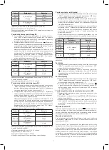
Rozsah
Přesnost
Odchylka
200 mV
±0,5 % z rozsahu
± 1 číslice
100 μV
2 V
±0,5 % z rozsahu
± 3 číslice
1 mV
20 V
10 mV
200 V
100 mV
600 V
±0,8 % z rozsahu
± 2 číslice
1 V
Vstupní impedance: 10 MΩ pro všechny rozsahy
Ochrana při přetížení: 250 V rms špičkového napětí na 200 mV
a 600 V rms na všech ostatních rozsazích.
Měření střídavého (AC) napětí
1. Připojte černý měřicí hrot do zdířky označené „COM“ a červený
vodič do zdířky označené „V/Ω“.
2. Přepněte na funkci označenou V~. Zvolte měřicí rozsah a připojte
měřicí hroty na místo, kde budete měřit střídavé napětí. Zobrazí
se příslušné hodnoty.


