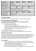
Specifications
OMS13/6
OMS13/10
OMS17/6
OMS17/10
Number of fiber inputs
1 (SC/APC)
Optical input power
−20 … +5 dBm
Optical wavelength
1270–1530 nm
1270–1530 nm
1270–1610 nm
1270–1610 nm
Number of coaxial outputs 6
10
6
10
Frequency Range
TERR 5–862 MHz; SAT 950–2150 MHz
Output Signal Level Range 50–95 dBuV (see table RF Signal level performance, page 3)
Current consumption*
150 mA
150 mA
180 mA
150 mA
Dimensions (w,d,h)
25.5 x 18.0 x 7.0 cm
Temperature Range
−25 … +50 °C
3) Product Takeover
Make sure that the product is not damaged. Please contact your dealer in the case of damage.
4) Product Storing and Installation
We recommend the device to be installed and serviced by the qualified technician.
The product must not be stored and installed:
•
in the place with excessive humidity
•
in the place with dropping or splashing water,
•
in the place with excessive dust pollution, mechanical vibrations or impacts
•
in the place out of temperature limits specified in the section 2) Technical Specifications
•
close to heat sources (radiators or air ventilators, direct sunshine etc.)
•
in the reach of children.
Use the apparatus only in moderate climates (not in tropical climate).
Fix the product firmly on a wall or another hard and inflammable surface with screws and dowels.
5) Product Connection
Connect the product in accordance with this manual and valid regulation. Use high-quality 75 Ω coaxial
cable designed for satellite reception. Mount the F connectors (screw, crimp or compress type) on the ends
of coaxial cables. Connect the F connectors into the F sockets of product and fasten them with an
appropriate force. The coaxial cables shall not be broken, the minimum bending radius should be 5 cm.
Fiber cable (recommended single mode) must be terminated with SC/APC connector.
Optical transmitter:
•
Connect F sockets marked “A” – “D” with LNB outputs (recommended LNB type is Quattro)
•
Connect input F socket marked “TERR” with output of terrestrial antenna, eventually with output
of terrestrial amplifier or channel processing equipment
•
Connect output SC/APC socket to other optical device (splitter, receiver)
•
Connect DC2.1 socket marked “DC 12V” with power supply
•
Connect connector marked with protective bounding symbol with protective bounding conductor
2 of 4


