background image

Impression Series 

Owner’s Manual

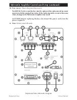
2.  Volume/Gain Control:

 The volume/level control should be at the minimum 

setting (all the way counter-clockwise) before plugging the subwoofer into an 

AC wall socket. Once plugged in, turn the level control up one quarter of a turn 

(9 o’clock position) for an initial setting. The level control may be adjusted while 

playing to match the subwoofer level with the rest of the system.


IMPORTANT! The volume control should be at the minimum setting (all the way 

counter-clockwise) before plugging the subwoofer into an AC wall socket.

3.  Crossover Frequency Control:

  The  variable  crossover  frequency  control 

allows you to set the low-pass crossover point of the subwoofer anywhere from  

40-180 Hz. If using this input experiment with setting the crossover frequency 

control at highest setting initially. Increasing the crossover frequency will allow 

more mid-bass output from the subwoofer. Decreasing the frequency will allow 

only deeper bass from the subwoofer.

  NOTE: 

Read the Important Notice regarding bass management on page 4.

4.  Auto Signal Tracking:

 The subwoofer amplifier uses “smart” signal tracking circuitry. 

Once the power cord is plugged in and the switch set to auto, the amplifier automatically 

turns on when a signal is detected at the preamplifier or high level inputs and turns off 

when no signal has been detected for 15 minutes.

5.  Phase Control:

 This control changes the phase of the subwoofer. Changing the 

phase will change the way the subwoofer and main speakers interact with each 

other at the crossover frequency. Varying the phase position may result in more 

or less mid bass depending on the phasing between the main speakers and the 

subwoofer. Generally, the phase is left at the “NOR (Normal)” position. 

6.  Low Level Line Output:

 These RCA terminals are for “daisy chaining” to another 

subwoofer or amplifier. A full-range signal is sent through these terminals.

7.  Low Level Line Input:

 Line level input is used to connect to most receivers or processors, 

use either the L or R terminals.

8.  Hi-Level Input:

 These binding post terminal connections are for the amplifier/

speaker level input from an amplifier or receiver. 


IMPORTANT! Use either the Line Input or the High Level Input. DO NOT 

use them both simultaneously.

9.  Hi-Level Output:

 This is a 100 Hz high-passed output for your satellite/main 

speakers. The crossover limits the low frequencies (below 100 Hz) from going to 

your satellite/main speakers. This crossover is active only when using the Hi-Level 

Input terminals. Connect your main speakers (observing the proper polarity) to 

these terminals when using the Hi-Level Inputs.

Subwoofer Amplifier Controls and Setup (continued)

Summary of Contents for IMPRESSION E55Ti

Page 1: ...FREESTANDING SPEAKERS IMPRESSION SERIES OWNER S MANUAL ...

Page 2: ......

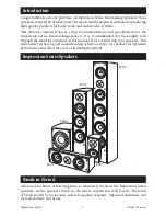
Page 3: ...hase of Impression Series freestanding speakers Your speakersaretheresultofmanyyearsofresearchanddevelopmentdedicatedtoproducing high quality products for home audio and audio video systems This manual contains features setup recommendations and specifications for the Impression Series freestanding speakers It is recommended you thoroughly read through the material contained in this manual before ...

Page 4: ...minimize driver interaction irregularities and maximize the ability of each driver to accurately reproduce its respective band of frequencies Five way binding posts ensure a solid electrical connection to these crossover networks The Impression Series speakers cabinets are constructed of inch medium density fiberboard because of its inert properties thereby minimizing sound coloration The front ba...

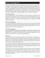
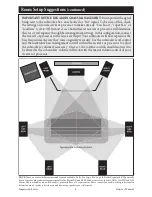
Page 5: ...tor The center channel speaker may be placed in a horizontal lying down or vertical standing position Rear Surround Speakers The 2 way bookshelf speakers may be placed either above behind or to the sides of the listening position The listening position should be centered between the surround speakers Forbestperformanceyoumaywanttoexperimentwithanglingthesurround speakers either towards or away fro...

Page 6: ...the subwoofer level control and the individual bass management control within the receiver or processor to adjust the subwoofers volume if necessary Once set the volume controls should not need to be altered as the subwoofers volume will track with the master volume control of your receiver or processor Impression Series 4 Owner s Manual NOTE There are several different surround formats available ...

Page 7: ...ld be connected to a power supply compatible with the power consumption requirements see the specifications section of this manual 5 If mounting the subwoofer on a stand the wall or other device only do so as recommended by an authorized technician 6 Place the subwoofer a safe distance from all heat sources such as radiators stoves or heaters 7 Do not operate the subwoofer near water for example n...

Page 8: ...y turnsonwhenasignalisdetectedatthepreamplifierorhighlevelinputsandturnsoff when no signal has been detected for 15 minutes 5 Phase Control This control changes the phase of the subwoofer Changing the phase will change the way the subwoofer and main speakers interact with each other at the crossover frequency Varying the phase position may result in more or less mid bass depending on the phasing b...

Page 9: ... event the fuse must be replaced the replacement fuse must match exactly the original fuse value If the replacement fuse is not of the same value damage to the Subwoofer Amplifier may result CAUTION Before replacing the fuse disconnect the power cord from the power receptacle 11 Power Power on and off switch Impression Series Subwoofer Diagram ...

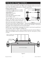
Page 10: ...e metal spike feet work best on carpeted surfaces The rubber cone feet have been included for use with wooden or tiled floors Attach the tower speaker outrigger plates to the bottom of the speaker with the machine screws provided as shown in figure 2 below The larger plate should be at the front of the speaker and the smaller plate at the back of the speaker NOTE To prevent scratching or damaging ...

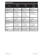
Page 11: ...207mm H 121 4 311mm D High gloss Red Burl or High gloss Black Ash 52 lbs 23 59 Kg E5Ti Tower 50Hz 20kHz 87dB 50 150 Watts 2 6 165mm Polypropylene 1 5 133mm Aluminized Poly matrix 1 1 25mm Fabric Dome 6 Ohms 120Hz 3000 Hz 81 2 216mm W 351 2 902mm H 121 4 311mm D High gloss Red Burl or High gloss Black Ash 35 lbs 15 88 Kg E5Ci Center Channel 60Hz 20kHz 87dB 50 120 Watts 2 5 133mm Aluminized Poly mat...

Page 12: ...gh gloss Red Burl or High gloss Black Ash 7 5 lbs 3 40 Kg Model Frequency Response Sensitivity Recommended Power Woofer Tweeter Impedance Crossover Frequencies Dimensions Includes Base Cabinet Weight ES10i Subwoofer 40Hz 180Hz N A 100 Watts 110 220V RMS Amplifier Power 1 10 254mm Poly matrix Cone N A N A 40Hz 180Hz 141 8 359mm W 15 381mm H 161 4 413mm D High gloss Red Burl or High gloss Black Ash ...

Page 13: ...quency by turning the crossover frequency control clockwise until the desired sound is obtained Solution Impression Series 11 Owner s Manual No sound from speakers No sound from one speaker Very little bass and or imaging Speaker wire not connected Speaker selector on amplifier is not on Balance control on receiver or pre amp is not centered Speaker wire not securely connected Speakers are wired o...

Page 14: ... com for detailed information on returns EMP Tek will at its option replace or repair the product free of charge and return the product by prepaid delivery This warranty does not apply to any product which has been damaged misused altered neglected or repaired by anyone other than an EMP Tek authorized service facility Any implied warranties including fitness for use and merchantability are limite...

Page 15: ......

Page 16: ...84041 Phone 801 991 1308 Fax 801 543 3300 www emptek com It is EMP Tek policy to continuously incorporate improvements into products all specifications are subject to change without notice Copyright 2010 EMP Tek LLC All Rights Reserved ...

Reviews: